the resistor value isn't quite right either. Hawksford's paper ([1], page 32) gives the optimal value equation, which I work out to be something around 10 ohms.
It depends on the circuit. The book value (10R) is probably based on the most basic Vbe multiplier (which is what you have when your tools are only paper and pencil), where it really depends on how you choose Rbc/Rbe ratio. In real circuit, Vbe multiplier can be complicated by addition of diodes and paralleled R (not to mention caps). But the good thing about using simulator is that you don't need to calculate, and in the end you may just be able to get rid of this unnecessary resistor.
FWIW I did simulate it, and it agreed with Hawkford's equation (9.6 ohms ideal).
In the end I decided not to change it under the presumption that the out-of-balance compensation networks for the upper and lower drivers might need adjusting, and JV did those by ear.
In the end I decided not to change it under the presumption that the out-of-balance compensation networks for the upper and lower drivers might need adjusting, and JV did those by ear.
this , archaic, but simple and cheap, always better than the big expensive bulky electrolytic
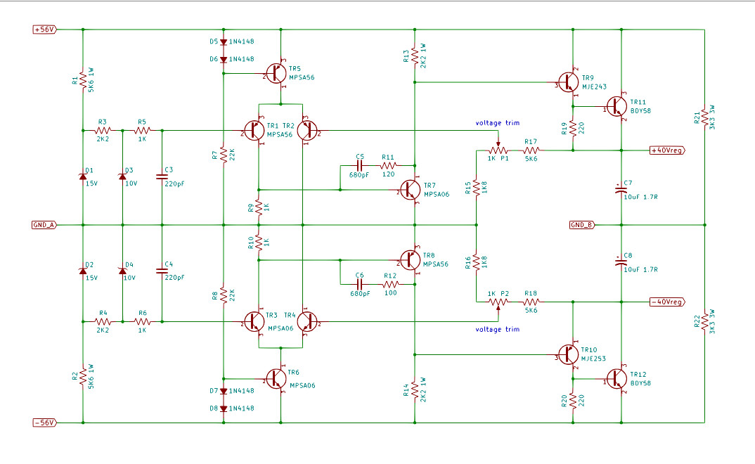
If you're looking to use something like the Naim regulator, it doesn't cost anything to invert the LTP and VAS so their references aren't the dirty power rails.
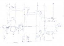
This schematic also adds a simple CCS for the LTP, but most of the performance gain over the original is due to inverting the LTP and VAS:
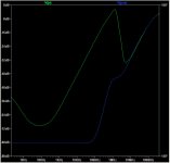
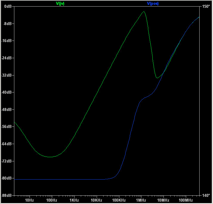
Here are the attenuation curves (original in green, above schematic in blue):
Cheers,
Jeff.
PS: idea is not mine; PigletsDad on PFM suggested it to me.
Attachments
FWIW I did simulate it, and it agreed with Hawkford's equation (9.6 ohms ideal)
What was the VAS current? What was Rbc? Rbe? Junction temperature?
In the end I decided not to change it under the presumption that the out-of-balance compensation networks for the upper and lower drivers might need adjusting, and JV did those by ear.
Even using simulator you need to be skillful to get to such precise values. Doing it by ears?? It's like choosing passive speaker crossover values using ears only.
If you're looking to use something like the Naim regulator, it doesn't cost anything to invert the LTP and VAS so their references aren't the dirty power rails.
This schematic also adds a simple CCS for the LTP, but most of the performance gain over the original is due to inverting the LTP and VAS:
Here are the attenuation curves (original in green, above schematic in blue):
Cheers,
Jeff.
PS: idea is not mine; PigletsDad on PFM suggested it to me.
interesting, thank you
The graphical comparison is important
but in the end what is more important in a final power amplifier?
- a nice scheme but stuffed with a cap or servant to check the offset
- a scheme of type 140 but revised in the quality of a capacitor (the input cap is eliminated)
- or a 140 model but fully stabilized in the input, driver and end VCC voltages?
- a nice scheme but stuffed with a cap or servant to check the offset
- a scheme of type 140 but revised in the quality of a capacitor (the input cap is eliminated)
- or a 140 model but fully stabilized in the input, driver and end VCC voltages?
What was the VAS current? What was Rbc? Rbe? Junction temperature?
Ivas 36mA, Rc 6.4ohms, Re 3.2ohms, Tj 25ºC.
Ivas 36mA, Rc 6.4ohms, Re 3.2ohms, Tj 25ºC.
My NAP clone vas current is 20mA. P3A is 5mA. You can optionally use higher Rbc/Rbe ratio. At such high current (and Asian countries), the temp can be higher. With such conditions you will get higher than 10R.
If you're looking to use something like the Naim regulator, it doesn't cost anything to invert the LTP and VAS so their references aren't the dirty power rails.
The references for the ltps are identical, the dirty rails, and it is okay. The vas could be better with your circuit. But i'm not convinced. For me the regulator is not about as much as regulating the supply voltage. How about other performances such as output impedance?

Good if he did. My LT Spice simulation predicts 28 ohms as optimum in a NAP, so the standard value of 27 is fine.Hehe, I was definitely referring to Douglas, "everything sounds the same if correctly engineered" Self. And I`m pretty sure he wouldn`t put his name to that NAIM even if his life depended upon it.
It is, however, in his book I noticed this first. I haven`t seen either Hawksford or the mentioned article by JLH. My copy of DS`book is unavailable now, but I`m pretty sure he used that very value, 27R i mean.
R
Last edited:
Clearly, as I could, I would stabilize this scheme, but it is not clonable🙁
Why do you want to clone that amplifier? Yes, the input JFET has no equivalent, but there are many ways to do the first stage with different part. The second stage is strange as the JFET Vds is very high. Doesn't have to be fet tho. Harder part imo is the complementary fet drivers. Nothing equals the J313 Toshiba parts which is hard to find. What amp is that? Spectral?
Why do you want to clone that amplifier? Yes, the input JFET has no equivalent, but there are many ways to do the first stage with different part. The second stage is strange as the JFET Vds is very high. Doesn't have to be fet tho. Harder part imo is the complementary fet drivers. Nothing equals the J313 Toshiba parts which is hard to find. What amp is that? Spectral?
I would like to clone it because it sounds very good.
there are no caps on the signal and it is coupled in DC with a very stable offset
The problem is precisely 2n 5566 to which I can not find a substitute
Tried to replace with a dual transistor, but I lose a lot.
The emitter follower with a j fet P-channel , Toshiba J 109, is very good for the amp
The scheme is Spectral revised by Norma Audio
.
if you have suggestions for the first stage, I am grateful
the original drivers were Hitachi 2SK 216 and complement 2SJ 79, no more products, but can be replaced.
My problem is the Dual j fet input and input stage
Last edited:
it could
I see it has a capacity of 25 pf instead of 12, the rest of the parameters looks good
We hear who understands it
I see it has a capacity of 25 pf instead of 12, the rest of the parameters looks good
We hear who understands it
Last edited:
I believe Johan Bernstrøm still have a few of these left.
And according to your latest drawing you planned a cascoded inputstage so the 25pF shouldn`t do much harm.
R
And according to your latest drawing you planned a cascoded inputstage so the 25pF shouldn`t do much harm.
R
The references for the ltps are identical, the dirty rails, and it is okay. The vas could be better with your circuit. But i'm not convinced. For me the regulator is not about as much as regulating the supply voltage. How about other performances such as output impedance?
Sloppy wording on my part. The LTP is inverted only because that's the easiest way to drive the inverted VAS.
Output impedance is also improved, again more-so in the upper frequencies. At 1KHz it goes from 1.5mOhms to 0.2mOhms; at 10KHz 10mOhms to 0.6mOhms.
I believe Johan Bernstrøm still have a few of these left.
And according to your latest drawing you planned a cascoded inputstage so the 25pF shouldn`t do much harm.
R
No
A somewhat eye-watering price, but: 2N5566 Integrated Circuits | Quest Components
one piece , two pieces totally
- Status
- Not open for further replies.
- Home
- Amplifiers
- Solid State
- Modified Naim NAP140 Schematic