But the NAP is attractive for DIY because it has relatively few parts
exactly
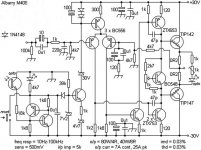
Glancing at the Albarry 408 schematic I would agree. I see many flaws. There is a mistake in the transistor labeling too as ZTX653 is npn and ZTX753 is pnp.
the design scheme Naim does not seem sophisticated, it seems rather, as indeed it is, taken from a Philips application notes of half a century ago
Then Naim climbed to make it stable, and the scattered compensations confirm it, not succeeding well: in fact, with power cables not Naim the final wavered
little or no attention to stabilize the offset if not sowing condensers everywhere
Spectral has a sophisticated and studied scheme, Acoustat Twin 200 as well, but they are irreproducible
Glancing at the Albarry 408 schematic I would agree. I see many flaws. There is a mistake in the transistor labeling too as ZTX653 is npn and ZTX753 is pnp.
I am not a technician, but I see a basic schematic, at maximum savings, prepared quickly, but not really bad as sound
Then that 4.7 Kohm of entry, mah, at least a 20 Kohm, 27 maximum ............
I will never understand why spread the 2 most important input differential transistors on the printed circuit:
is not it better to select them and put them attached to try to control the offset?
and put a trimmer on emitters?
mah
Clear that seeding some electrolytic cap all succeeds elementary
Last edited:
the design scheme Naim does not seem sophisticated, it seems rather, as indeed it is, taken from a Philips application notes of half a century ago
To appreciate a design i think we must have good ears. Because the sound we create is a result of some Physics at work. This is very complex because how things relate to sound perception is not a public knowledge. Topology does not tell anything. But to design the best amp I will not choose LTP input because i don't want to apply feedback like normally done with LTP input.
I look at the 140 cloned for the reasons repeatedly exposed, not to redo the Naim sound that I don't like much
I also cloned the Naim. Not to redo the sound but to improve it. Retaining its strength and improve its weakness.
In post 1 I`m pretty sure TR7s driving elements, 680R and 560R are supposed to be connected to TR5 collector. Otherwise the inclusion of the 27R resistor is rendered moot.
I believe the good DS advocated this neat little trick.
Regards
R
I believe the good DS advocated this neat little trick.
Regards
R
true, it would become my scheme, but I would have a few more watts, better if doubling the power pair from 1 pair to 2
I delete the input capacitor or I use a Mundorf type, I see if with a dual BJT input and a trimmer on the emitter I can better control the offset (I just do not understand why placing the 2 transistors of the IN differential one here and there there else, not even in thermal contact)
I would also make it stabilized in the entry stages, drivers and finals
I could get a good result with a few €
Paralleling output just to get more power is wrong. There is sound compromise from doing so if the transistor is not matched.
Putting the differential transistors in thermal contact is not always critical. An LTP is rarely a balanced circuit. It is not necessary balanced especially if power supply is regulated like in Naim.
What do you mean with stabilized entry, driver and final? Stability is a function of gain and phase and how the operating point changes by environment changes such as temperature. On this, indeed the Naim is poor. Can be easily improved.
No. Have a think about what the purpose of the 27 ohm resistor is.In post 1 I`m pretty sure TR7s driving elements, 680R and 560R are supposed to be connected to TR5 collector. Otherwise the inclusion of the 27R resistor is rendered moot.
I believe the good DS advocated this neat little trick.
Regards
R
If by DS you mean Doug Self then I'm not a fan. I don't think he could correctly explain the Naim circuit to save his mother.
I agree. 🙂To appreciate a design i think we must have good ears. Because the sound we create is a result of some Physics at work. This is very complex because how things relate to sound perception is not a public knowledge. Topology does not tell anything.
No. Have a think about what the purpose of the 27 ohm resistor is.
If by DS you mean Doug Self then I'm not a fan. I don't think he could correctly explain the Naim circuit to save his mother.
I'm curious about this too. I don't have Self, but Cordell and Hawksford both present it as a method of compensating for increased bias spread with increased VAS current.
But not only is the upper driver taken off at the wrong point for that, the resistor value isn't quite right either. Hawksford's paper ([1], page 32) gives the optimal value equation, which I work out to be something around 10 ohms.
So I'm thinking perhaps this isn't what it's for after all. @Traderbam, can you give us a hint?
[1] https://www.researchgate.net/profil...638/Audio-Amplifier-Systems-A-Compilation.pdf
The simple answer is the Vbe transistor is less linear if the temperature increases and more collector current is via a fixed amount source like a CCS.
Since the latter is connected to the bias resistors of the Vbe transistor and the base of the upper driver transistor and the impact of temperature change is out of step with the audio signal it makes sense to put some limit on the share of current drawn by the Vbe collector to prevent any micro form of "hunting".
If you want another reference for this type of set up, Linsley-Hood used this in his 75W amplifier published in Hi-Fi News and Record Review back in November 1972
Hehe, I was definitely referring to Douglas, "everything sounds the same if correctly engineered" Self. And I`m pretty sure he wouldn`t put his name to that NAIM even if his life depended upon it.
It is, however, in his book I noticed this first. I haven`t seen either Hawksford or the mentioned article by JLH. My copy of DS`book is unavailable now, but I`m pretty sure he used that very value, 27R i mean.
R
It is, however, in his book I noticed this first. I haven`t seen either Hawksford or the mentioned article by JLH. My copy of DS`book is unavailable now, but I`m pretty sure he used that very value, 27R i mean.
R
To appreciate a design i think we must have good ears. Because the sound we create is a result of some Physics at work. This is very complex because how things relate to sound perception is not a public knowledge. Topology does not tell anything. But to design the best amp I will not choose LTP input because i don't want to apply feedback like normally done with LTP input.
I'm interested in something that sounds discreetly
What sounds good, I think, I just can not do it again because I can not find the fet
that's why I look at the 140, as already mentioned, simple and clonable without problems
Clear that the flaws of the 140 are different, but, at the end, you can try to limit them
Paralleling output just to get more power is wrong. There is sound compromise from doing so if the transistor is not matched.
Putting the differential transistors in thermal contact is not always critical. An LTP is rarely a balanced circuit. It is not necessary balanced especially if power supply is regulated like in Naim.
What do you mean with stabilized entry, driver and final? Stability is a function of gain and phase and how the operating point changes by environment changes such as temperature. On this, indeed the Naim is poor. Can be easily improved.
sure that to parallel the power transistors I no longer have power, but more capacity to supply current
In order to increase the apotency I have to increase the VCC
In fact hceedevo if someone had already done and with what results
input, driver and final power stage stabilized I intend to precede input and driver from a stabilizer that always delivers 40 vcc
idem the final power stage, insomm a, adjust the voltage VCC
Last edited:
this , archaic, but simple and cheap, always better than the big expensive bulky electrolytic
While this regulator circuit has been used by Naim in their NAP250 it has also been used in an Adcom high power amplifier. Nelson Pass did some design work for that company.
While this regulator circuit has been used by Naim in their NAP250 it has also been used in an Adcom high power amplifier. Nelson Pass did some design work for that company.
ah, I did not know that also Pass ...........
in any case, this from Naim is always a good stabilizer
it exists better, much better as a Norma, but this is simple, cheap and quick to implement
with these stabilizers recovery the waste from the selection of the final transistors
Last edited:
- Status
- Not open for further replies.
- Home
- Amplifiers
- Solid State
- Modified Naim NAP140 Schematic