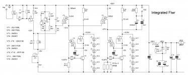
Here I propose an extension of shunt approach to an integrated amplifier.
Every of the three stages are based on shunt principle.
The first staged provides voltage amplification (I tested it on a breadboard, Ku approximately = 6).
The second stage is a driver stage, with output impedance of few Ohms.
The output stage is based on the well affordable IRFP150.
Every of the three stages are based on shunt principle.
The first staged provides voltage amplification (I tested it on a breadboard, Ku approximately = 6).
The second stage is a driver stage, with output impedance of few Ohms.
The output stage is based on the well affordable IRFP150.
Attachments
Antonio,
I would not do that, that function is safely carried out by R6. The TL431 is configured at just bellow its maximum rate of 36 V and will provide a stable voltage. For me personally, a meticulous regulation is not of primary importance. Let´s cautiously expect satisfactory results in that regard.
I would not do that, that function is safely carried out by R6. The TL431 is configured at just bellow its maximum rate of 36 V and will provide a stable voltage. For me personally, a meticulous regulation is not of primary importance. Let´s cautiously expect satisfactory results in that regard.
Hello Vladimir,
Yor observation regarding use of multiple small output caps instead of one big cap is very interesting. Did you ever consider using non-polar ouput caps, considering that they tend to have much lower distortion?
If you use a doublesided board with one copper plane for plus and one for minus you can almost eliminate those parasitic inductances and get a much faster cap bank that should have an inductace similar to a single small cap.
P.S. How would you describe the sound of the Allen Bradley resistors ? (Sorry if I overlooked your previous comments)
Yor observation regarding use of multiple small output caps instead of one big cap is very interesting. Did you ever consider using non-polar ouput caps, considering that they tend to have much lower distortion?
I can foresee objections again a cluster of small caps, because of bigger parasitic inductance induced by assembling structure. One must not be afraid of this parasitic inductance, ...
If you use a doublesided board with one copper plane for plus and one for minus you can almost eliminate those parasitic inductances and get a much faster cap bank that should have an inductace similar to a single small cap.
P.S. How would you describe the sound of the Allen Bradley resistors ? (Sorry if I overlooked your previous comments)
MRupp,
the dominant cause, which is the inductive reactance of the winding and its terminals (giving high impedance) cannot be "eliminated" with any kind of board.
the dominant cause, which is the inductive reactance of the winding and its terminals (giving high impedance) cannot be "eliminated" with any kind of board.
WuYit
Why is there no capacitance to ground on the output the regulator , is the capacitance possibly part of the next stage, or is this intentional?
Thanks
-Antonio
Why is there no capacitance to ground on the output the regulator , is the capacitance possibly part of the next stage, or is this intentional?
Thanks
-Antonio
It`s not intentional, just forgotten. The capacitors in the diagram only indicate location; polypropylene would be nice, aiming high frequencies. Vcemax for 2SA1475 (probably a hard-to-find type anyway) is 120 V, I´m not able to find a suitable PNP device, should be a video transistor, regulator performance strongly relies on it. Unfortunately, it will be difficult to set a proper bias current.
Last edited:
Hello Vladimir,
Yor observation regarding use of multiple small output caps instead of one big cap is very interesting. Did you ever consider using non-polar ouput caps, considering that they tend to have much lower distortion?
If you use a doublesided board with one copper plane for plus and one for minus you can almost eliminate those parasitic inductances and get a much faster cap bank that should have an inductace similar to a single small cap.
P.S. How would you describe the sound of the Allen Bradley resistors ? (Sorry if I overlooked your previous comments)
I tried non-polar Mundorf electrolytics, and was not encouraged for further use. From the measurement side (dissipation angle), they are also like ordinary.
With doublesided board is a correct solution, it is a patented solution, aimed at computer mainboards design. However in audio, IMHO, PURE indictances, even if parasitics, do not make sound dark and dull, while electrolytics tend to make it, due to properties other than parasitic inductance. Designing audio, we usually use theoretical models that do not include various details, minor level effects.
With Allen Bradley resistors I am satisfied, they need some burn-in.
Vladimir....I sort of have the feeling that your integrated version sounds even better than the separate boxes..as you reduce interfaces and capacitors...A better and stronger concept... A critical component must be the VT5...must be low in capacitance...
michael
michael
I tried non-polar Mundorf electrolytics, and was not encouraged for further use.
I had not those in mind, too bulky, especially the non-etched version, but rather bibolar versions of standard radial elkos. I am currently using Frolyt EKSU 220µF, same as here (sorry, in German) in a alephono clone and am planning on trying them as output caps.: http://www.frolyt.de/FROL_DB2_2010_08_31.pdf . Other manufacturers also make some non-polar versions of their caps, including ELNA who offer bipolar versions of their Silmic II capacitors on demand, though I presume you would need to buy in quantity.
Ok, I understand your position. I am not sure about the patent but Rifa showed this in an application guide, it is a method used for sharing high ripple currents among capacitors when a normal bus bar would fail. The guide has disappeared from the WEB pages, Rifa seems to have been completely swallowed by Kemet, but here is a post where you can see the relevant page: http://www.diyaudio.com/forums/chip...t-any-comments-suggestions-10.html#post560038With doublesided board is a correct solution, it is a patented solution, aimed at computer mainboards design. However in audio, IMHO, PURE indictances, even if parasitics, do not make sound dark and dull
Vladimir....I sort of have the feeling that your integrated version sounds even better than the separate boxes..as you reduce interfaces and capacitors...A better and stronger concept... A critical component must be the VT5...must be low in capacitance... michael
Now, after some adjustments, the first stage gives amplification Ku=11 with R5=5k1, R3=133k, R2 and C1 have been canceled, schematic is dead stable without them.
Important also the presence of Zener substitute VT3-VT4, without it simple common source stage never sounds good.
I agree with you about requirements for VT5, I hope that I have managed to get right parts for this position , 2SK2199 have Ciss=80pF with nealy 1S transconductance.
I plan to test the amp without output stage, as headphones amp first, or as a preamp.
Last edited:
I had not those in mind, too bulky, especially the non-etched version, but rather bibolar versions of standard radial elkos. I am currently using Frolyt EKSU 220µF, same as here (sorry, in German) in a alephono clone and am planning on trying them as output caps.: http://www.frolyt.de/FROL_DB2_2010_08_31.pdf . Other manufacturers also make some non-polar versions of their caps, including ELNA who offer bipolar versions of their Silmic II capacitors on demand, though I presume you would need to buy in quantity.
Ok, I understand your position. I am not sure about the patent but Rifa showed this in an application guide, it is a method used for sharing high ripple currents among capacitors when a normal bus bar would fail. The guide has disappeared from the WEB pages, Rifa seems to have been completely swallowed by Kemet, but here is a post where you can see the relevant page: http://www.diyaudio.com/forums/chip...t-any-comments-suggestions-10.html#post560038
Thanks for sharing. I guess, we always must look for better caps and test them, and their proper assembly also important. I would like to use double sided teflon, for the cap assembly.
I have measured impedance modulus vs frequency dependencies for various electrolytic caps, and got obvious support for using of a cluster of low-impedance capacitors, SamWha WL in this example.
As it is known for decades, capacitors suffer from electro-mechanical resonances, adding to sound distortions ecpecially in the 5-20kHz region.
From this picture, one can see measured impedance bumps in this region, and this bump is almost absent in case of the low-ESR cap.
As it is known for decades, capacitors suffer from electro-mechanical resonances, adding to sound distortions ecpecially in the 5-20kHz region.
From this picture, one can see measured impedance bumps in this region, and this bump is almost absent in case of the low-ESR cap.
Attachments
Last edited:
I have assembled 24pcs of SamWha WL 1000uFx63V, as two 12pcs rings, in order to ensure equal signal path distance to each cap.
The measured impedance curve is approximated by the three-parameter cap model
Zc=1/jwC; ZL=jwL; ZR =R; |Z| = sqrt[R*R+(Zc-ZL)*(Zc-ZL)]
Important is, that the measured impedance curve has no resonance-induced bumps in the audio range, however, the resonance bump happens in the range 20...500kHz.
I have noticed, that touching and bending of the outgoing wires, affects Z measurement within few percents. I conclude, this cluster configuration, in distinction to the previously measured Nichicon 10000uF cap, can be safely used with good result in the frequency range up to 5...10kHz. Important also, that regular Nichicon electrolytic cap was measured without any long outgoing wire, just by connecting to its short leads.
For higher frequencies, I plan to add 2x470uF Elna Cerifine + 100uF polypropylene caps. And additional inductance in series with the SamWha cluster should be added, in order to limit the frequency range of its operation.
Attachments
Last edited:
Interesting results.
in this case also this thread could be of interest:
http://www.diyaudio.com/forums/parts/151392-best-electrolytic-capacitors.html
in this case also this thread could be of interest:
http://www.diyaudio.com/forums/parts/151392-best-electrolytic-capacitors.html
Interesting results.
in this case also this thread could be of interest:
http://www.diyaudio.com/forums/parts/151392-best-electrolytic-capacitors.html
Thank you, tiefbassuebertr, that is an interesting thread started by Nelson Pass. It is a bit pitty, that thread has ended by the simulation curves only. As for me, most important is to look for those parasitic parameters and their effect, that are not included in simulation models.
Also important, at the level of tenths mOhms, impedance is affected by every tiny assembling details, apart from cap's various parasitic properties.
In my measurements, 100uF Solen polypropylene cap at any frequency has impedance modulus higher than the cluster of SamWha WL caps. So, putting polypropylene into effective participation in signal currents transmission, definitely needs a kind of crossover scheme.
hello Vladimir,
I like your cap-cluster board.
How much those SamWha WL caps cots?
I have some SamWha's 4700uF/100V, here it cost 6 Euro
I like your cap-cluster board.
How much those SamWha WL caps cots?
I have some SamWha's 4700uF/100V, here it cost 6 Euro
hello Vladimir,
I like your cap-cluster board.
How much those SamWha WL caps cots?
I have some SamWha's 4700uF/100V, here it cost 6 Euro
Hello, Goran
With all dealer margins and post expencies, those SamWha WL 1000uFx63V costed me almost 1 Euro/pcs. Their manufacturer price I guess close to 30 cents.
I would also advise to check for SamWha WB series, a bit better than WL.
One should pay attention to the series notion, since the manufacturer name says nothing about characteristics.
That's not expensive at all. Could You gave me the data of that dealer?
It was parts distributor in russia, Ýëèòàí - êîìïîíåíòû âûñîêèõ òåõíîëîãèé
For reading the site in english, try the following
Google Translate
Measurement-wise, I still can not improve the impedance curve of these 24-cap cluster. Adding of polypropylene
1) 1x100uF
2) 7x6u8
or in combination with 470uF Elna Cerafine
3) 1x100uF + 470uF
4) 1x100uF + 2x470uF
5) 7x6u8 + 470uF
With any of the indicated shunt variants the impedance curve does not go below the cluster-only impedance, except for the variant 2), where it gives smaller impedance at 100kHz-1MHz, but also strong resonant impedance peak at 50kHz
- Status
- Not open for further replies.
- Home
- Amplifiers
- Solid State
- Modified Follower-99 With HF Transistors