I did the trimming of the horn edges and measured. No impact whatsoever.
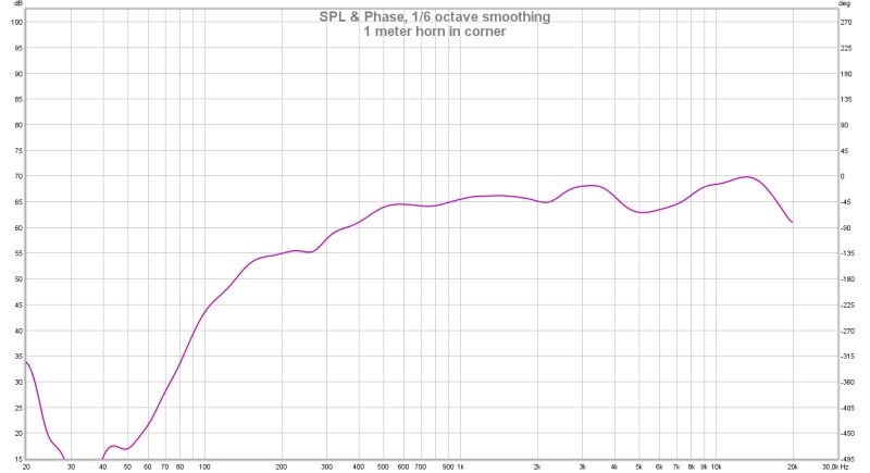
Next I measured with the sealed back chamber heavily filled with fiberglass, then opened the back and left the fiberglass, then took all the fiberglass out (and of course kept the back cover off too). Below are the overlays at 5 cycles and 10 cycles.
Some takeaways:
1) The dip at 2.2kHz is always there.
2) There is basically no difference between sealed back chamber and open back with fiberglass on. At least on frequency response. The back chamber is not yet dialed in to annul the reactance, though.
3) Empty open back may or may not be better. I know Pooh likes it this way. I want to listen to the system both ways once its up and running. From 400Hz onwards (my target xo point) there is no difference on frequency response.
Reactions?
Attachments


A quick search of the thread shows that cone breakup hasn't been mentioned yet. I looked at the manufacturers response and there is a dip between 2-3k as POOH has already suggested. 2k might be a good place to stop expecting too much?
On a more productive note, it may be time for more information. A polar plot has the information needed to differentiate a chamber/axial resonance, from diffraction and can identify the useable parts of the breakup region.
It's hard to say how much of horizontal/vertical/diagonal would be necessary but anything may be useful.
I'm hoping to be able to take some polar measurements tomorrow night.
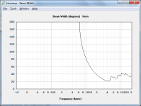
In the meantime, a side question: I played around with Hornresp to understand the impact of reducing the mouth size, allowing length to vary so to keeep fc constant. To my surprise, both predicted responses pretty much the same...so what gives?
S1------S2-------L12------SPL@2500Hz Beamwidth@2500Hz
90cm2 1990cm2 32.2cm- 101.3dB------- 48°
94cm2 1200cm2 31.3cm- 101.5dB------- 46°
A 1200cm2 mouth horn is 40% smaller than the 1990cm2. What is the downside to a smaller horn?? The upside would be smaller center-to-center distance to the tweeter, and higher WAF.
The down side of a smaller mouth is low frequency ripple due to the unloading of the horn. This is easy to see in the acoustic impedance plot in Hornresp. In addition, the horn also gets shorter. At minimum you want the circumference of the mouth to be one wave length of the lowest frequency you wish the horn to reproduce. Length should be at least 1/4 a wave length of the lowest frequency you wish the horn to produce. However, better results are had when you make the length (1/4WL)/0.7071
The drop at 2KHz is the mass rolloff of the driver plus the voice coil inductance and the front chamber volume choking off the high frequencies. The raise back up is most likely due to the narrowing directivity. This can be confirmed, or debunked by polar measurements.
The drop at 2KHz is the mass rolloff of the driver plus the voice coil inductance and the front chamber volume choking off the high frequencies. The raise back up is most likely due to the narrowing directivity. This can be confirmed, or debunked by polar measurements.
Attachments
I'll also add that when using a horn like this for dedicated mid range use, it is best to use a horn with a Fc 1/2 the desired low frequency. So in your case a 200Hz is about what you should shoot for. From previous discussions you can compromise on this by sizing the horn between (1/2Fc)/0.7071 and (1/2Fc)/0.618
However, horn coloration might start to become noticeable near cutoff. Everything is a compromise. When in doubt, go bigger.
However, horn coloration might start to become noticeable near cutoff. Everything is a compromise. When in doubt, go bigger.
Bruce Edgar used a slot around the edges of the driver. I have done that myself and used washers between the horn and the driver this leak reduces the output in the lower range and then the rellative output of the higher range is brought up a bit.
I just might bring out my 3 sets of cone driven mid range horns and start to measure again 😉
An other option would be to use a cap to get a 6 dB slope below 2 kHz to flatten the response. By adding a resisitor across the driver the hump at the bottom might be adjustable
I just might bring out my 3 sets of cone driven mid range horns and start to measure again 😉
An other option would be to use a cap to get a 6 dB slope below 2 kHz to flatten the response. By adding a resisitor across the driver the hump at the bottom might be adjustable
Last edited:
The down side of a smaller mouth is low frequency ripple due to the unloading of the horn. This is easy to see in the acoustic impedance plot in Hornresp. In addition, the horn also gets shorter. At minimum you want the circumference of the mouth to be one wave length of the lowest frequency you wish the horn to reproduce. Length should be at least 1/4 a wave length of the lowest frequency you wish the horn to produce. However, better results are had when you make the length (1/4WL)/0.7071
Hello JLH! Very glad you joined.
That's a great tip.
I had previously learnt from you I should design a horn with fc=200Hz if my intended range started at 400Hz, which is the case.
At 400Hz the wavelength is 86.3cm, so minimum circunference is 86.3cm and minimum length (.25*WL/0.7071)= 30.5cm.
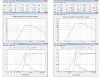
The smaller model, with S2=1200cm2 and 2:1 width:height ratio, is 49x24.5cm. Assuming I can use perimeter of the rectangle in place of circumference, then perimeter is 147cm (or 1.7 times WL @ 400Hz). Likewise, length is 31.3cm vs 30.5cm minimum. So the smaller horn satisfies the minimum requirements. But larger is better, hence the 1990cm2 mouth horn would be even better. Right? Might I be overkilling by going with the 1990cm2 horn?
Below I pasted Hornresp output for the larger horn on the left, and the smaller one on the right. I can see the blue ripples on the right having larger amplitude than those on the left, which I guess can't be good. Also noticeable is a more pronounce valley on SPL around 500Hz (coincident with the largest dip in the impedance.
I'll do my best to take some polar measurements tonight and will look forward to your feedback.The drop at 2KHz is the mass rolloff of the driver plus the voice coil inductance and the front chamber volume choking off the high frequencies. The raise back up is most likely due to the narrowing directivity. This can be confirmed, or debunked by polar measurements.
Attachments
The drop at 2KHz is the mass rolloff of the driver plus the voice coil inductance and the front chamber volume choking off the high frequencies. The raise back up is most likely due to the narrowing directivity. This can be confirmed, or debunked by polar measurements.
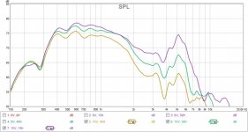
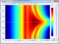
I don't know how to multi-quote here, but to address the above and AllenB's comment above, I took some polar measurements.
First a note since this is the first time I do this with a horn: I'm measuring angles from the centerline of the mouth, not the driver. So 30 degrees off-axis from the mouth is not really 30 degrees off from the driver...just wondering...
Vertically I only took on-axis and 15 degrees off because that is as high as my mic tripod would go. I thought going below axis would also capture floor reflections...
Help me interpret the curves. What do you read from them?
Attachments
Shameless bump 😀
Would love to get feedback on
A) Interpretation of the curves from post #88. What do you read from them?
B) Do you think the smaller horn mentioned on post #87 would be too small? In other words, would the increased throat impedance ripples be too high and detrimental to sound quality vs the larger version?
I'm eager to advance to an improved "dummy" build, but need to boil down conclusions from this iteration to take good advantage of having built it. 😱
Looking forward to your input!
Personally I prefer rectangular high frequency horns. I haven't heard a round horn that I liked. Technically, a Tractrix horn should be round, but I prefer the sound of a rectangular Tractrix over a round one.
This is exactly how I feel although I did hear some round horns that I liked. We conducted not a very scientific experiment whereby we switched a rectangular 300Hz Tractrix horn (1:1,5 ratio, placed vertically) with 300Hz round tractrix horn with everything else remaining the same. And then we switched back. And we did this several times. The switching only took minutes because both horns had JBL 2441 already attached to them. The differences in sound were subtle. The one thing that clearly stood out was the superior imaging of the rectangular horn. I reported this to my horn guru, Dr. Bruce Edgar, with whom I have been rubbing elbows for the last couple of decades and he gave me a good scientific explanation why the horns sounded the way they did which went right above my head. And that's alright - I'm not an engineer, just a hobby audiophile. But the finding was enough for me to forever say good-by to round horns in the mid-range.
For higher frequencies you could get a broad idea of the performance by modelling H and V separately, for example V as shown below. In this case the parameters are correct for only one plane (middle top to bottom, ie length 32cm, width 31.5cm conical as per your first post), which I then applied as if it were axissymmetrically so. The overall expansion is wrong and so the lower frequency information and the impedances etc, but the directivity may still be helpful above this region.
Modelling the horizontal for higher frequencies is another story. The overall expansion may be tractrix (to lower frequencies) but what is your actual horizontal curve in this form?
..
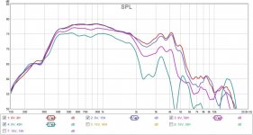
Your measured data seems to show some lobing around 1500Hz. As this is the first obvious issue I would consider it a reasonable assumption that you could cross below this point at this stage of development. Above 2k the response narrows considerably, but appears to have second thoughts at 3k.
The issue appears to smooth somewhat above the horizontal plane so I'd guess that the top/bottom are contributing. If this happens to be due to diffraction I'd at least give some thought to a roundover for higher frequencies. Again easy enough to test with temporary baffling and measuring back on the horizontal plane to keep the vertical errors in focus.. but the issue may also be from within the horn.
Modelling the horizontal for higher frequencies is another story. The overall expansion may be tractrix (to lower frequencies) but what is your actual horizontal curve in this form?
..
Your measured data seems to show some lobing around 1500Hz. As this is the first obvious issue I would consider it a reasonable assumption that you could cross below this point at this stage of development. Above 2k the response narrows considerably, but appears to have second thoughts at 3k.
The issue appears to smooth somewhat above the horizontal plane so I'd guess that the top/bottom are contributing. If this happens to be due to diffraction I'd at least give some thought to a roundover for higher frequencies. Again easy enough to test with temporary baffling and measuring back on the horizontal plane to keep the vertical errors in focus.. but the issue may also be from within the horn.
Attachments

Last edited:
Shameless bump 😀
Would love to get feedback on
A) Interpretation of the curves from post #88. What do you read from them?
B) Do you think the smaller horn mentioned on post #87 would be too small? In other words, would the increased throat impedance ripples be too high and detrimental to sound quality vs the larger version?
I'm eager to advance to an improved "dummy" build, but need to boil down conclusions from this iteration to take good advantage of having built it. 😱
Looking forward to your input!
The combination of mass roll off, voice coil inductance, and front chamber compliance is clearly limiting the high frequency output to about 1.8KHz. The hole between 1.8KHz and 3KHz was being filled in by the narrowing directivity of the horn. The peaks that occur at higher frequencies is from cone break up artifacts exciting the horn at those frequencies. This is what the polars are telling me.
Lewinski sorry for the off topic. A question for JLH.
JLH in your 8PE21 tapped horn if I remember correctly you said the Fs of the 8PE21 was lowered. Does the mass cutoff change because of the lower Fs or is it dependent on the original Fs? Thanks.
SMathews
JLH in your 8PE21 tapped horn if I remember correctly you said the Fs of the 8PE21 was lowered. Does the mass cutoff change because of the lower Fs or is it dependent on the original Fs? Thanks.
SMathews
The Edgar trick of a gap between the driver and horn throat filled with scotchbrite scouring pads seems to have worked quite well for Kees - his tractrix with Visaton 3.5in driver is getting pretty smooth wide reach. No EQ results here - passive high pass cap used I think. In the Trynergy thread.
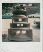
This is a picture of some prototype radial horns circa 1976 that I did. The mid horns were made using 10" cones, single and double, and were loaded 25% of actual effective cone area. What I will tell you is that as you increase the loading the bandwidth narrows and becomes more peaked in the center of the bandwidth. The back chambers were very small, they were based on the Paul Klipsch equation that if I remember correctly was X=2.9AR or 2.9 x's the area x's the rate of expansion. That equation was based on an exponential expansion but should still be valid for a tractix or other horn flare. It extends the low frequency cutoff. Much of this work is covered in my very old patent#4369857 which about 20 companies use as reference for many horn developments today. I used hyperbolic expansion rates as I liked that better than a plain exponential expansion rate. If you want the widest bandwidth with the least ripple in the band use a throat equal to the cones working diameter, usually the inside diameter of the surround and you will be best off. My rear chambers were domed shaped, no flat back wall to be reflective like you are describing a half sphere if you can do it that fits tightly around the cone driver. You do have to calculated fairly accurately the actual displacement of the driver you are using and add that to the rear volume. Just a few pointers from and old horn waveguide designer.
Attachments
Last edited:
Your measured data seems to show some lobing around 1500Hz. As this is the first obvious issue I would consider it a reasonable assumption that you could cross below this point at this stage of development. Above 2k the response narrows considerably, but appears to have second thoughts at 3k.
Thanks for the input. Could you explain how do you see/conclude there is lobing at 1.5kHz? Honest question, so I can learn what to look for/at in the future.
This tells me the horn is not suited for what I needed it to do. Instead of limiting the range I'd rather look at improving the horn. The crossover point could be between 2 and 2.5kHz, but below 2kHz becomes unacceptable to me.
The issue appears to smooth somewhat above the horizontal plane so I'd guess that the top/bottom are contributing. If this happens to be due to diffraction I'd at least give some thought to a roundover for higher frequencies. Again easy enough to test with temporary baffling and measuring back on the horizontal plane to keep the vertical errors in focus.. but the issue may also be from within the horn.
The roundover you refer to would be using the existing horn and closer to the driver? Aproximating an axisymmetrical horn close to the driver and transitioning to a rectangular cross section?
Lewinski sorry for the off topic. A question for JLH.
JLH in your 8PE21 tapped horn if I remember correctly you said the Fs of the 8PE21 was lowered. Does the mass cutoff change because of the lower Fs or is it dependent on the original Fs? Thanks.
SMathews
It's based on the free air resonance, or in your words the original Fs.
Go Big !!
In this project, the goal is simply to "lift up" the response between 200-400Hz, and to provide some sense of directivity to match the tweeter. The naked response is already pretty good, save for the previously mentioned octave.
As JLH has already pointed out, the extended downward response is important for phase matching between the lower range of the horn, and the mid bass drivers below.
This will take a larger horn throat than what would normally be used. The larger throat will also allow the upper range to be less constricted than what it is now.
http://www.faitalpro.com/products/files/M5N8-80/12/M5N8-80_curves_12.pdf
Last edited:
I believe this works, in part at least by minimising the maximum reflected distance via the back wall. Some research has shown me that radar cross sections are analogised to the size a reflective sphere which reflects the same amount of EM energy, implying that while a sphere of any size may appear to have an infinitely small region of direct specular reflection, that this isn't the case in practice while wavelengths are finite.My rear chambers were domed shaped, no flat back wall to be reflective like you are describing a half sphere if you can do it that fits tightly around the cone driver.
The combination of mass roll off, voice coil inductance, and front chamber compliance is clearly limiting the high frequency output to about 1.8KHz. The hole between 1.8KHz and 3KHz was being filled in by the narrowing directivity of the horn. The peaks that occur at higher frequencies is from cone break up artifacts exciting the horn at those frequencies. This is what the polars are telling me.
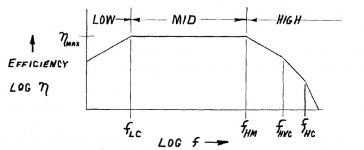
The schematic you posted on #84 made me go back to Keele's 1977 AES paper.
Per my design, fc is 215Hz. Keele assumes fc is "very much lower" than fLC...BUT for this driver:
- Back cavity compliance roll-off: fLC= QTS*fs/2=0.45*180/2=40Hz...so from the get go this isn't complying with key assumptions Keele made...
- Mass rolloff frequency: fHM=2*fs/QTS=800Hz.
- Voice coil inductance corner: fHVC=Re/(pi*Le)=15279Hz. High Re, and low Le
- Front cavity compliance: fHC=2*QTS*fs*(VAS/VF). Here VF is the volume of the front cavity. Assuming that is the same as Atc in Hornresp, then 100cm3, and fHC=1944Hz.
Mass rolloff and voicecoil inductance seem ok to my [untrained] eye. It seems to me fHVC (a driver property) is high enough to allow for a horn that can play to 2.5kHz without trouble.
Front cavity compliance seems too low. Actually very close to the region where you all are seeing issues. Intuitively this seems as something that should be adjustable by adjusting horn design. But fHC is defined by driver parameters only. Am I missing something?
How should I modify the horn design to improve response up to 2.5kHz?
- Home
- Loudspeakers
- Multi-Way
- Midrange horn design, cone-driven - 201