This is a picture of some prototype radial horns circa 1976 that I did.
Nice picture! Especially with the cars in the back.
What is your point of view regarding aspect ratio (width:height) of rectangular horns and their sound quality? My prototype is 2:1, and I've seen people also touting 1.5:1. In my mind the tradeoff is with center-to-center distance to the tweeter.
OK, throat=Sd will be adopted for my next prototype. How about mouth size? Will the increased impedance ripples in the 1200cm2 mouth horn be very noticeable vs those from the 1990cm2 mouth horn (based on the Hornresp simulations posted above)?
I understand the domed back of the rear cavity is a concave dome as seen from the driver, right?
The 30 degree pressure measurement converges with the axial pressure measurement giving the impression of a change in wavefront shape. It may be the physical convergence of a higher order mode at your measurement distance. I'd be guessing. It may not be significant and it may not be audible, but it may indicate the potential for further higher order modes above this frequency.Thanks for the input. Could you explain how do you see/conclude there is lobing at 1.5kHz?
Low frequencies trace the horn expansion but the highs are more susceptible to the wall curvature. There is a reason the shape you have chosen is worthwhile and works..but it can expose some compromising issues at the top end.The roundover you refer to would be using the existing horn and closer to the driver? Aproximating an axisymmetrical horn close to the driver and transitioning to a rectangular cross section?
The narrow vertical directivity of the top/bottom walls doesn't mean that a shorter mouth dimension is necessarily appropriate, sometimes the opposite. While you noted the smaller horn option seems to work there are considerations beyond what seems intuitive in hornresp. Eg, modelling in half space might show you how the horn would behave when terminated on to a baffle, it's up to you to discover whether baffling is the appropriate kind of termination.
At higher frequencies the termination method may be simpler but can be more important if you run the horn out sooner. Using a short and compromised mouth to decrease driver spacing can be a false economy.
I wasn't suggesting you start axissymmetrical but that is one way to do it. There are many considerations.
Lewinski,
The designs you see later morphed into something much more complex that I called a hyperbolic exponential elliptical radial horn shape. The typical pinch or step at the joint of the side walls to the throat area was taken out but the flare still followed the hyperbolic expansion rate. The horn mouth would end up becoming and elliptical shape. The only other person I know who would have understood this back then was Earl Geddes who beat me to a patent and I have seen very similar ideas from him in his patents. I don't believe he ever commercialized his designs, just wrote a patent paper as far as I know. That downward slope at the transition from the throat to the flare angle is just a consequence of a fudge or connecting the two sections together and an attempt to somewhat follow an exponential expansion. I assure you there is a discontinuity in the connection of the two sections.
As to the aspect ratio I also preferred the shorter horn over a fully round horn lens for the same reason you noted which is the distance from center to center of stacked multiple horns. Don't forget at the time I was working with Pro-audio and not home stereo type of systems and this becomes a much greater problem when you are stacking multiple horns one on top of another in very large arrays. On you question of the curved back yes that would be concave as seen from the driver. It doesn't have to be completely spherical but should have a curvature to it and when you actually see how small the rear chamber should be it becomes very difficult to fit a shape around the back of the magnetic motor assembly without making it some part of a spherical shape. There will be little additional air space behind the driver to match the front horn if done correctly.
That was my 1974 450SEL Mercedes in the background. Great car, best car ever, went 500,000 miles with that car.
How should I modify the horn design to improve response up to 2.5kHz?
Use a larger throat. Place a layer of felt on the top and bottom slant boards.
Use a larger throat. Place a layer of felt on the top and bottom slant boards.
How large? Throat size = Sd OK?
What is the purpose of the felt?
The 30 degree pressure measurement converges with the axial pressure measurement giving the impression of a change in wavefront shape. It may be the physical convergence of a higher order mode at your measurement distance. I'd be guessing. It may not be significant and it may not be audible, but it may indicate the potential for further higher order modes above this frequency.
Thanks for the explanation. What tests could I do to confirm the lobing hypothesis?
Low frequencies trace the horn expansion but the highs are more susceptible to the wall curvature. There is a reason the shape you have chosen is worthwhile and works..but it can expose some compromising issues at the top end.
The narrow vertical directivity of the top/bottom walls doesn't mean that a shorter mouth dimension is necessarily appropriate, sometimes the opposite. While you noted the smaller horn option seems to work there are considerations beyond what seems intuitive in hornresp. Eg, modelling in half space might show you how the horn would behave when terminated on to a baffle, it's up to you to discover whether baffling is the appropriate kind of termination.
At higher frequencies the termination method may be simpler but can be more important if you run the horn out sooner. Using a short and compromised mouth to decrease driver spacing can be a false economy.
I wasn't suggesting you start axissymmetrical but that is one way to do it. There are many considerations.
Good hint about baffling as termination. I'll give it some thought.
I'm wondering about a smaller horn, maybe 1200 or 1300cm2 mouth (vs 1990cm2), and 1.5:1 aspect ratio instead of 2:1. With throat = Sd. I'm thinking su ch a horn would probably have a close-to square section throat (I'm guessing introducing less diffraction into the higher ranges) and keeping the tractrix expansion (to contiinue loading the lower end as this one does). Am I off thinking along those lines?
The Edgar trick of a gap between the driver and horn throat filled with scotchbrite scouring pads seems to have worked quite well for Kees - his tractrix with Visaton 3.5in driver is getting pretty smooth wide reach. No EQ results here - passive high pass cap used I think. In the Trynergy thread.
Sorry I just realized I never replied. Saw it on my phone and thought about it, but forgot to reply. I remember reading about the trick on Edgar's midrange horn article. I was under the impression it helped with the lower range of the midrange horn, though. Did I get it wrong?
How large? Throat size = Sd OK?
What is the purpose of the felt?
If you increase St to Sd, your high frequency output will start to fall at around 1Khz. The circumference resulting from a throat area of 94.2cm^2 is equal to about 1 wave length at 1KHz. Once you enlarge the throat to a circumference greater than 1 wave length of your highest desired frequency you start to lose efficiency. However, how much you lose depends on too many variables to speculate. Its better to try it and see what happens. Phase plug, or gluing a 4" diameter dust cap to the cone are possible alternatives to reducing the front chamber volume.
If you increase St to Sd, your high frequency output will start to fall at around 1Khz. The circumference resulting from a throat area of 94.2cm^2 is equal to about 1 wave length at 1KHz. Once you enlarge the throat to a circumference greater than 1 wave length of your highest desired frequency you start to lose efficiency. However, how much you lose depends on too many variables to speculate. Its better to try it and see what happens. Phase plug, or gluing a 4" diameter dust cap to the cone are possible alternatives to reducing the front chamber volume.
Thank you.
Not sure if you got to see my post #100 above. Would love to get your point of view on it. Here's a copy:
The schematic you posted on #84 made me go back to Keele's 1977 AES paper.
Per my design, fc is 215Hz. Keele assumes fc is "very much lower" than fLC...BUT for this driver:
What does this mean?
- Back cavity compliance roll-off: fLC= QTS*fs/2=0.45*180/2=40Hz...so from the get go this isn't complying with key assumptions Keele made...
- Mass rolloff frequency: fHM=2*fs/QTS=800Hz.
- Voice coil inductance corner: fHVC=Re/(pi*Le)=15279Hz. High Re, and low Le
- Front cavity compliance: fHC=2*QTS*fs*(VAS/VF). Here VF is the volume of the front cavity. Assuming that is the same as Atc in Hornresp, then 100cm3, and fHC=1944Hz.
Mass rolloff and voicecoil inductance seem ok to my [untrained] eye. It seems to me fHVC (a driver property) is high enough to allow for a horn that can play to 2.5kHz without trouble.
Front cavity compliance seems too low. Actually very close to the region where you all are seeing issues. Intuitively this seems as something that should be adjustable by adjusting horn design. But fHC is defined by driver parameters only. Am I missing something?
How should I modify the horn design to improve response up to 2.5kHz?
Regarding Post #100. Keele's math is for when everything is ideal. In the real world things will be a little off. However, from performing the math I see the numbers reflect very well with the measurement. From the measurement the front chamber volume/compliance is the nail in the coffin. The mass roll off, voice coil inductance and front chamber volume have an additive effect on the high frequency response. By the time you hit the frequency range where the front chamber comes into play, the horn is pretty well done. You can try to replicate what Avantgarde Acoustic does. They add a large dust cap to the cone of the driver to reduce the front chamber volume. Of course there is a mass penalty to pay, but how much will have to be tested for.
Attachments

How large? Throat size = Sd OK?
What is the purpose of the felt?
No, you want it even larger, say 6x6 for 36 sq. inches.
A conventional horn is not what you need for this driver. This driver is not well suited to a conventional horn. Too much mass roll off. Also, you don't need much
of an increase in gain, just a little "lift" in the lowest operating octave.
Trust me, 99 db/watt flat across your desired spectrum will drive you out of the room, if you let it. If we can trust the published curves of this driver, the subdued response is right at the ear's most sensitive range, and will go a long way towards reducing the cone "shout" that otherwise emanates from ruler flat response. The felt is placed on the flats to reduce (or hopefully eliminate) slap echo. I'm thinking the walls of quick flare tractrix curve get out the the way fast enough, plus having a super sized throat helps. Think of this as more of a waveguide, than a horn. If you want a true, REAL true horn mid range, then you are better off with a 2 inch compression driver and a horn well matched to it, but good luck getting down to 500Hz, unless the horn is quite large. It is also a great idea to baffle mount this "horn". A 10 inch depth, with a 23.5 wide x 17.25 tall mouth is where I would start. I'm thinking Volvotretter's site has a tracrix curve calculator, if not, I'm sure you can find one somewhere, to help you plot the curves.
I don't want to disagree here but I don't believe a smaller throat will increase the high frequency output. What you really have with a front chamber is a low pass filter, the larger it is the lower the pass frequency, hence the drawing that JLH just showed with the dust cap filling the majority of that chamber is to decrease the volume of that chamber. If you want the flattest bandwidth leave the chamber at the Sd size. If you were using a compression driver you would certainly not decrease the throat size at the connection to the throat that just causes a reversion wave and has nothing to do with using a cone driven horn loaded mid. Getting down to 500hz with a compression driver and mid horn has been done forever, not a real issue in a home at normal spl levels.
I haven't seen a write up on extrapolating higher order mode details through measurement alone, though it can be done. I'd consider making temporary changes to track down the issues.Thanks for the explanation. What tests could I do to confirm the lobing hypothesis?
For what it's worth I think LeCleach shows the way to terminate this style of horn in a way that offers size benefits. A baffled horn of this type can sound closed in.Good hint about baffling as termination. I'll give it some thought.
Maybe. If size is your priority then settling for directivity only in the top end might be where you are at. Blending the horn back into the tweeter is an option.smaller horn, <snip> I'm thinking such a horn would probably have a close-to square section throat (I'm guessing introducing less diffraction into the higher ranges)
I don't want to disagree here but I don't believe a smaller throat will increase the high frequency output. What you really have with a front chamber is a low pass filter, the larger it is the lower the pass frequency, hence the drawing that JLH just showed with the dust cap filling the majority of that chamber is to decrease the volume of that chamber. If you want the flattest bandwidth leave the chamber at the Sd size. If you were using a compression driver you would certainly not decrease the throat size at the connection to the throat that just causes a reversion wave and has nothing to do with using a cone driven horn loaded mid. Getting down to 500hz with a compression driver and mid horn has been done forever, not a real issue in a home at normal spl levels.
Exactly, that's why I recommended a larger throat. Also, we don't want flat across the bandwidth gain. This driver does not need it.
Regarding Post #100. Keele's math is for when everything is ideal. In the real world things will be a little off. However, from performing the math I see the numbers reflect very well with the measurement. From the measurement the front chamber volume/compliance is the nail in the coffin. The mass roll off, voice coil inductance and front chamber volume have an additive effect on the high frequency response. By the time you hit the frequency range where the front chamber comes into play, the horn is pretty well done.
This is great! Thank you so much.
So front cavity compliance is indeed a driver property, which is what you target by adding the dustcap you propose.
You can try to replicate what Avantgarde Acoustic does. They add a large dust cap to the cone of the driver to reduce the front chamber volume. Of course there is a mass penalty to pay, but how much will have to be tested for.
This is a great idea! I wasn't aware Avantgarde did this. I thought of a phase plug, but never thought of this one.
Why a large dustcap instead of a phase plug, though? Not that I favor phase plugs, but they seem to be two alternative approaches of tackling a similar issue and wanted to benefit from your experience. Probably practical limitations for the DIYer come into play.
Kindhornman and Scott L both make valid points. The majority of what I wrote was in regards to obtaining the highest sensitivity. If 99dB is enough, then what Scott L mentioned is true and has been done with success by others on here. If you are looking to just boost the low end than this is a perfectly acceptable solution. However, I've seen it done more often with a square or rectangular throat that has the corners such that the suspension is exposed. Only a very small area of the cone is covered by the horn throat.
I think my comments about the smaller throat might have missed the mark because I did not go into enough detail. In a classical horn alignment the smaller the throat the higher up in frequency the horn gain will be. Of course for reasons of simplicity we will assume that the front chamber volume has been dealt with and it isn't made worse. The reason why a smaller throat provides more high frequency gain is because the pressure wave front compresses the air and it becomes a better media for transferring acoustical energy. True horn gain (not directivity gain) begins when the horn has a dimension that is acoustically small in comparison to the wave length. This can also be observed in Hornresp.
We got a little lost between theory and the practical example we are working with. If we were to just make the throat smaller and make no other changes, then things would get worse because it would actually make the front chamber volume larger.
Why a large dustcap instead of a phase plug, though? Not that I favor phase plugs, but they seem to be two alternative approaches of tackling a similar issue and wanted to benefit from your experience. Probably practical limitations for the DIYer come into play.
The dust cap is a lot easier. The results of a properly designed phase plug will be better, but a lot harder to execute. While I'm not 100% convinced, it is said that the dust cap shape will launch a spherical wave front instead of a flat plane wave. In theory it should match up to the throat of the tractrix horn really well.
Yes. It has also been said that a dome will radiate a forward moving wave which resembles a spherical wave in shape only at the start, that requires the horn to tease it out.While I'm not 100% convinced, it is said that the dust cap shape will launch a spherical wave front instead of a flat plane wave.
Required Sensitivity
Answering how much is the minimum required sensitivity is not that straight forward. I think I should shoot for 102-103 dB @ 1m, 2.83V. Your feedback will be helpful too.
The tweeter is a TPL-150H to be used above 2kHz, and in that range it displays a sensitivity around 101-102dB.
My intent is for a fully active system (OK, an intermediate step is a passive xo between tweeter and midrange, but final goal is fully active), where the tweeters are driven by a SET and the midranges are driven by another SET. Ideally a 45 SET, but could be 2A3 too. To sound their best, I understand SETs should be driven up to 50% of their rated power, and even better if kept below 25%. A 45 is rated for 2W, so I assume I'll use up to 1W.
At 1W max and 102dB @ 1m, one driver will deliver 102dB SPL at 1m. Add about 4.5dB for a second driver (the L/R) and that's 106.5dB @ 1m. Listening distance is 2.4m, so at that point SPL will be reduced to 98.9dB. Add about 4.5dB for room gain and the SPL at the listening point in the room is estimated to be 103.4dB. Is this enough? Not sure.
I usually listen at around 85dB SPL measured at the listening position. Ocasionally up to 90dB. I understand ideally I want to have 20dB headroom for peaks, so 90+20=110dB. Would I be compromising too much with 13dB headroom? Maybe. Or go to 2A3 and add another dB or two SPL.
Bottom line: I think I need 102-103dB. What do you think?
Unfortunately I didn't measure the current prototype at 2.83V. Hornresp predicts 102dB points at 285 and 2100Hz and 104dB or more between 330 and 1275Hz, for the axisymmetrical equivalent.
Kindhornman and Scott L both make valid points. The majority of what I wrote was in regards to obtaining the highest sensitivity. If 99dB is enough, then what Scott L mentioned is true and has been done with success by others on here. If you are looking to just boost the low end than this is a perfectly acceptable solution. However, I've seen it done more often with a square or rectangular throat that has the corners such that the suspension is exposed. Only a very small area of the cone is covered by the horn throat.
Answering how much is the minimum required sensitivity is not that straight forward. I think I should shoot for 102-103 dB @ 1m, 2.83V. Your feedback will be helpful too.
The tweeter is a TPL-150H to be used above 2kHz, and in that range it displays a sensitivity around 101-102dB.
My intent is for a fully active system (OK, an intermediate step is a passive xo between tweeter and midrange, but final goal is fully active), where the tweeters are driven by a SET and the midranges are driven by another SET. Ideally a 45 SET, but could be 2A3 too. To sound their best, I understand SETs should be driven up to 50% of their rated power, and even better if kept below 25%. A 45 is rated for 2W, so I assume I'll use up to 1W.
At 1W max and 102dB @ 1m, one driver will deliver 102dB SPL at 1m. Add about 4.5dB for a second driver (the L/R) and that's 106.5dB @ 1m. Listening distance is 2.4m, so at that point SPL will be reduced to 98.9dB. Add about 4.5dB for room gain and the SPL at the listening point in the room is estimated to be 103.4dB. Is this enough? Not sure.
I usually listen at around 85dB SPL measured at the listening position. Ocasionally up to 90dB. I understand ideally I want to have 20dB headroom for peaks, so 90+20=110dB. Would I be compromising too much with 13dB headroom? Maybe. Or go to 2A3 and add another dB or two SPL.
Bottom line: I think I need 102-103dB. What do you think?
Unfortunately I didn't measure the current prototype at 2.83V. Hornresp predicts 102dB points at 285 and 2100Hz and 104dB or more between 330 and 1275Hz, for the axisymmetrical equivalent.
Regarding Post #100. Keele's math is for when everything is ideal. In the real world things will be a little off. However, from performing the math I see the numbers reflect very well with the measurement. From the measurement the front chamber volume/compliance is the nail in the coffin. The mass roll off, voice coil inductance and front chamber volume have an additive effect on the high frequency response. By the time you hit the frequency range where the front chamber comes into play, the horn is pretty well done. You can try to replicate what Avantgarde Acoustic does. They add a large dust cap to the cone of the driver to reduce the front chamber volume. Of course there is a mass penalty to pay, but how much will have to be tested for.
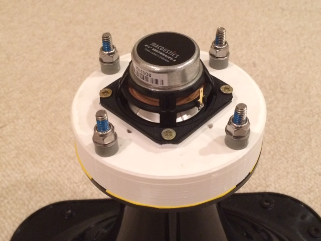
What Bushmeister and I found out when we were working on adapting a commercial WG for use with a fullrange driver is that it matters a lot how smooth the transition of the cone to throat is. If you have a sharp edge there, it will cause a cancellation dip at throat characteristic frequency determined by throat size and the speed of sound. However, if a very smooth and gradual throat chamber-to-throat transition is made (possible with a lathe or 3d printing), a very good performance can be had. The stiffness/damping of the cone also makes a difference too (SB65WBAC25-4 with aluminum cone and large plastic dustcap seems to work exceedling well).
More info here:
http://www.diyaudio.com/forums/multi-way/285030-bookshelf-multi-way-point-source-horn.html
Here is the throat chamber adapter I made with 3d printing:
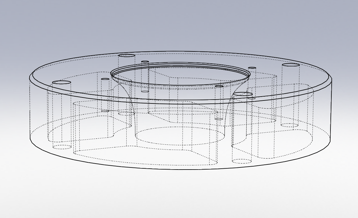
Internals of it:
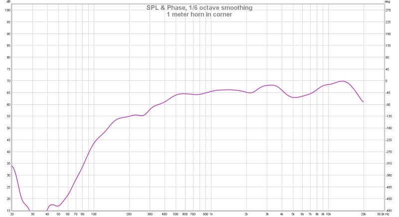
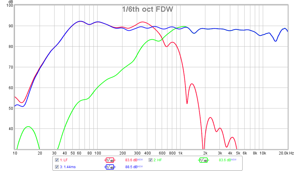
And here is the resulting frequency response in a LTH142 waveguide (1.4in throat) with the SB65 driver - the smooth chamber almost eliminated the 4.5kHz and 9kHz dips:
I tried 3 different throat chamber profiles, short to long an it turned out the medium one was the best with a smooth profile. It's unclear how this works as I would have thought the shorter length would have a smaller front chamber volume and higher upper reach, but it turned out to be the medium length one.
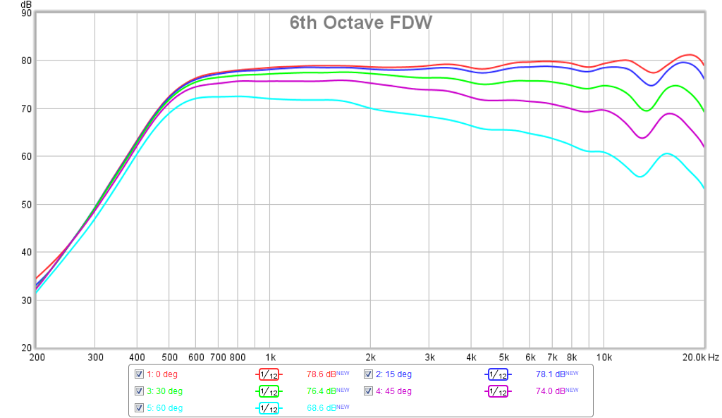
Adding the woofers it looks like this:


Here is the overall response (Harsch XO) once the woofer bandpass holes were added - running dual 7in woofers and a sealed box rear chamber:
- Home
- Loudspeakers
- Multi-Way
- Midrange horn design, cone-driven - 201