Lewinski,
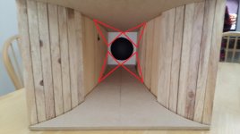
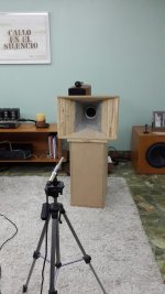
Myself I would just use Bondo body filler to shape the first section of the horn from the cone on out. I also never agree that you want to make square corners in your rectangular mouth shape, continue the radius out to the end of the horn. A nice large roundover at the mouth will help to limit the diffraction that all horns that terminate with an abrupt cutoff will have. I would just build the horn and leave the dust cap off at first, you can glue it on with rubber cement later and see if you can tell a difference, I highly doubt it except for some loss of high end due to the extra mass you will be adding to the cone, You are not creating a compression driver so that is one reason I doubt highly that the dust cap will make any real improvement. You can look at the horn as if it has flat planar waves emanating from the cone but I assure you that is a false premise and just makes the modeling simpler. Keep it simple for now, learn and later you can try something more challenging. I am assuming from your pictures that the rear chamber is much to large.
PS, I am going to make a judgement call and tell you that with that large rear chamber that you will find the cone will hit the back side of the horn mounting surface, you will more than likely need to make a spacer ring to keep that from happening.
Last edited:
Not sure if this was inspired by my comments, by the way I agree. My point was to help construct a mental picture of how the horn elements fit into the hornresp picture.You can look at the horn as if it has flat planar waves emanating from the cone but I assure you that is a false premise and just makes the modeling simpler.
Allen,
I didn't direct that at anything you said, just a comment about how so many think that is the case with flat planar waves in a horn. If it was only that simple. I also think many people assume that a wave will fill in the sharp square corners of a rectangular horn shape.
I didn't direct that at anything you said, just a comment about how so many think that is the case with flat planar waves in a horn. If it was only that simple. I also think many people assume that a wave will fill in the sharp square corners of a rectangular horn shape.
I agree with the suggestions about the throat being too large. I would recommend the throat be made square and such that the side walls are the same width as the cone opening. Then fill the corners to make a smooth transition to the rectangular mouth. The dust cap will add a negligible amount of mass to the driver. When I've build similar horns, I go into it knowing I might trash the cone of the driver if it doesn't work out. However, the knowledge gained far out weights the cost of a recone kit. Recone kits aren't that expensive.
Attachments
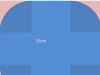
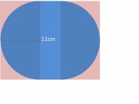
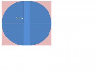
Not sure if I'm making myself clear about what my plan is. The plan is to fill the angles along the first 23cm of axial length with a filler such that the white plate will not be seen anymore, except for a 1cm wide ring around the throat.
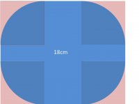
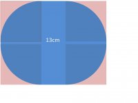
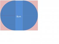
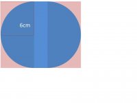
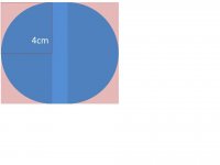
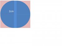
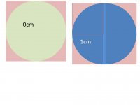
I'm attaching a schematic of the cross-sections every 1cm along the axial length. The blue area is the horn cross-section. The red is filler, and the rectangular edges around it are the edges of the wooden horn you see in the above pictures.
At 0cm, or S1, it's painted green because that is a circle. That circle is 94.2cm2 (same as Sd), or 11cm diameter. The white plate seen in the pictures above has a 9cm diameter opening, thus the 1cm ring one would see.
What do you think? Am I on a bad track?
Attachments
-
 Slide23.JPG17.7 KB · Views: 71
 -
 Slide18.JPG22.6 KB · Views: 67
 -
 Slide13.JPG21.1 KB · Views: 54
 -
 Slide11.JPG21.2 KB · Views: 62
 -
 Slide8.JPG20.5 KB · Views: 60
 -
 Slide6.JPG19.6 KB · Views: 65
 -
 Slide4.JPG19.2 KB · Views: 283
 -
 Slide3.JPG18.4 KB · Views: 283
 -
 Slide2.JPG19 KB · Views: 286
 -
 Slide1.JPG23.4 KB · Views: 296
Lewinski,
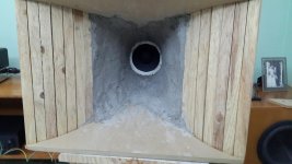
That looks like the very first horn throat I ever did with hand calculated math for a round to square transition. If you are using the inside of the surround as the Sd dimension what I will predict it that the surround will slap the back of the horn mounting flange. You will need to make a spacer ring to fit between the back of the horn and the frame of the driver to keep that from happening. Been there, done that!
That looks like the very first horn throat I ever did with hand calculated math for a round to square transition. If you are using the inside of the surround as the Sd dimension what I will predict it that the surround will slap the back of the horn mounting flange. You will need to make a spacer ring to fit between the back of the horn and the frame of the driver to keep that from happening. Been there, done that!
Yes, I noticed you mentioned this before and I'm keeping it in mind. I have a hard time understanding how could that happen when the distance from surround to back of the mounting flange is smaller than the driver's Xmax, but since you've been there I'm going to keep my eyes open.
Somewhat related, I'm more concerned with the dustcap hitting the 45 degree cutout, as it is close to Xmax. Still, per the simulations the driver should never come close to Xmax, but...
This PM it will be Filler Time here Hopefully worth the effort! Luckily it's raining 😉
Somewhat related, I'm more concerned with the dustcap hitting the 45 degree cutout, as it is close to Xmax. Still, per the simulations the driver should never come close to Xmax, but...
This PM it will be Filler Time here
Hopefully worth the effort! Luckily it's raining 😉Lewinski,
I think what you will find is that the Xmax is an electrical property showing the maximum linear motion but doesn't necessarily mean that the driver will not attempt to actually exceed this value. There is no physical limit to the voicecoil jumping out of a gap or hitting a back plate. One solution is to use a steep high pass filter that will limit the lower frequency response of the driver you are using. If you are only counting on physical limitations while doing actual acoustical testing the test signal should be band limited or you will go below the Fs of the driver and then you will see what I am talking about, excursion will not be controlled. I'm only trying to make you aware that things do happen that aren't predicted by the simple electrical models.
I think what you will find is that the Xmax is an electrical property showing the maximum linear motion but doesn't necessarily mean that the driver will not attempt to actually exceed this value. There is no physical limit to the voicecoil jumping out of a gap or hitting a back plate. One solution is to use a steep high pass filter that will limit the lower frequency response of the driver you are using. If you are only counting on physical limitations while doing actual acoustical testing the test signal should be band limited or you will go below the Fs of the driver and then you will see what I am talking about, excursion will not be controlled. I'm only trying to make you aware that things do happen that aren't predicted by the simple electrical models.
Somewhat related, I'm more concerned with the dustcap hitting the 45 degree cutout, as it is close to Xmax. Still, per the simulations the driver should never come close to Xmax, but...
😉
It probably will be so stupid loud if that happens you won't hear it. 😱
I'm working on converting a 230 flare 60x40 expo radial horn over to be used with 4-5" cone. If I get it done soon I'll do some measurements.
2nd prototype
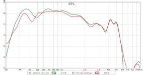
I was able to make some progress with the new horn iteration. To summarize the horn design:
You might recall I got a dustcap to afix to the cone, yet these measurements are without the dustcap. That will be a next step. I first want to draw conclusions from this trial.
What do you think?
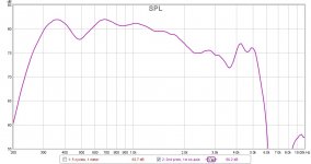
I'm thinking above about 1.7kHz both performances are equally poor. Of course this is what the dustcap is supposed to improve. My takeaway is without a dustcap I might be OK crossing over at 2kHz, but not higher. Also worth noting is the cement job didn't do much in this region, which is the region where it could have had some impact.
The lower end is puzzling. The wood horn reaches lower much better than the foam horn, but displays that wide valley centered around 480Hz...puzzling
FWIW 480Hz has a wavelength of 72cm...shorter than the height of the driver to floor...half a WL is 36cm vs mouth width of 33cm...I don't know. I'm shooting in the dark.
What do you think is causing the dip centered around 480Hz?
I was able to make some progress with the new horn iteration. To summarize the horn design:
- The goal is to cross it over somewhere in 400-500Hz and 2-2.5kHz.
- Based on learnings from the foam prototype above I reduced S2 and introduced the white flange to reduce Atc, while keeping S1 large.
- On Hornresp I modelled a tractrix with F12=185Hz, limiting S2 to 1667cm2.
- Using a 1.5:1 length:width ratio and roundings of the corners such that the cross-section at any given point equalled that of an axisymmetric tractrix, I applied cement and used a piece of wood cut to the specified radius to get the roundings. Not too pretty, but should be effective given what I learned above.
You might recall I got a dustcap to afix to the cone, yet these measurements are without the dustcap. That will be a next step. I first want to draw conclusions from this trial.
What do you think?
I'm thinking above about 1.7kHz both performances are equally poor. Of course this is what the dustcap is supposed to improve. My takeaway is without a dustcap I might be OK crossing over at 2kHz, but not higher. Also worth noting is the cement job didn't do much in this region, which is the region where it could have had some impact.
The lower end is puzzling. The wood horn reaches lower much better than the foam horn, but displays that wide valley centered around 480Hz...puzzling
FWIW 480Hz has a wavelength of 72cm...shorter than the height of the driver to floor...half a WL is 36cm vs mouth width of 33cm...I don't know. I'm shooting in the dark.
What do you think is causing the dip centered around 480Hz?
Attachments

The peaks (of the wood horn response) might be caused by the lack of mouth termination in vertical direction. Without proper termination, there could be a standing wave between throat and mouth. Foam appears to be lossier, so peaks are also less pronounced.
My guess is that the valley at 450 hz is a floor bounce null mitigated by the absorption of the carpet. Good, heavy pile carpet with a relatively open back on a .5" felt pad can have an absorption factor of .57 but its hard to translate absorption factor into depth of null. Intuitively, if the reflection comes in 180 out of phase and at half the strength of the direct path, it will cancel have the direct signal resulting in a 3 db depression.
Initially I thought the same, but the math isn't backing up my reasoning: The driver and mic are 83cm from floor. The mic is 100cm away from the mouth, and the horn is 34cm long, so driver to mic is 134cm.
So the distance from driver to floor bounce and back to mic is 213cm. A 162Hz wavelength is 213cm, so an 81Hz is half wavelength at 213cm, and 40Hz is 1/4 WL at 213cm...but the dip is centered around 450Hz...where am I loosing it?
So the distance from driver to floor bounce and back to mic is 213cm. A 162Hz wavelength is 213cm, so an 81Hz is half wavelength at 213cm, and 40Hz is 1/4 WL at 213cm...but the dip is centered around 450Hz...where am I loosing it?
Lewinski,
Take the horn outside and point it straight up and place the mic above the mouth opening on a suitable mic stand. If the same response is seen it is in the horn and not from the environment. If you wanted to get anal about it you could dig a hole and place the mouth of the horn at the ground level and measure that. Another things you can do in room is move the horn vertically with the mic still on axis and see if the dip shifts in frequency.
Take the horn outside and point it straight up and place the mic above the mouth opening on a suitable mic stand. If the same response is seen it is in the horn and not from the environment. If you wanted to get anal about it you could dig a hole and place the mouth of the horn at the ground level and measure that. Another things you can do in room is move the horn vertically with the mic still on axis and see if the dip shifts in frequency.
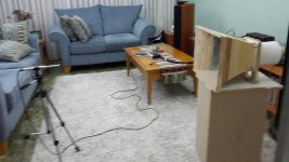
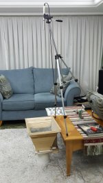
I like this idea! Taking everything outside entails a 1-hour drive each way...so last night I took a shortcut to verify directionally. See picture below. I placed the horn on the floor, pointing up, and placed the mic 1m away from the mouth. First reflection points are further away than before.
There is still a dip, but it has moved down in frequency. I'm guessing this suggests the dip is a cancellation from a reflection, right?
But how come the foam horn didn't display this?
There is still a dip, but it has moved down in frequency. I'm guessing this suggests the dip is a cancellation from a reflection, right?
But how come the foam horn didn't display this?
Attachments
Interesting experiment would be to go back to that first measurement setup and move the horn closer to or further away from the wall behind it; perhaps the same spacing you have from the floor in this picture.
My guess was going to be an axial standing wave between the throat and mouth termination (someone else suggested this too). It's plausible that the coffee table is modifying this. This measurement also adds some weight to the thought that it isn't the room.
A wild idea, what if you rest the bottom panel on the floor so the horn leans back and upturn the coffee table over the top panel?
A wild idea, what if you rest the bottom panel on the floor so the horn leans back and upturn the coffee table over the top panel?
- Home
- Loudspeakers
- Multi-Way
- Midrange horn design, cone-driven - 201