What Bushmeister and I found out when we were working on adapting a commercial WG for use with a fullrange driver is that it matters a lot how smooth the transition of the cone to throat is. <snip>
Looks outstanding. Congratulations!
Would you happen to have a picture of the driver + dustcap + adapter assembled? I think I could introduce a variation of this concept in my next prototype.
Mouth Size
As the many inputs sunk in, I played around with Hornresp a bit more and I'm coming to some conclusions which I''d like to bounce against you.
Mouth Size
I learnt once you go beyond the minimum size, the trade-off with a smaller mouth is increased ripples in the acoustic impedance. And center-to-center distance to the tweeter is a compromise I will need to live with - and see if I can live with it once up and running.
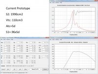
The current mouth is 1990cm2 at 2:1 aspect ratio, leading to 63 x 31cm. A bit too wide for my living room.
Adopting a 1.5:1 aspect ratio seems to have some merit. Leads to a square S1, and seems a better approximation of an axisymmetrical horn. Plus some reports favoring this ratio.
Attached are 4 simulations:
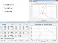
On 2) the highest amplitude ripple happens at 475Hz. Since this crossover point is going to be active and very steep (like 8th order), and targeted at 400hz, it seems at 475Hz the response is going to be diminished already. The 1667cm2 mouth horn is looking like a good compromise to me. What do you think?
BTW 1667cm2 was chosen arbitrarily, starting with 50cm wife-acceptable width and applying 1.5:1 aspect ratio.😀
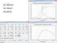
My attempt at modelling with the dustcap was just reducing Vtc from 110 to 30cm3. I was surprised to find almost no difference in simulated performance both on frequency response SPL and acoustic impedance. A 0.2dB lowering of the higher end response with 30cm3 vs 110cm3...odd isn't it?
As the many inputs sunk in, I played around with Hornresp a bit more and I'm coming to some conclusions which I''d like to bounce against you.
Mouth Size
I learnt once you go beyond the minimum size, the trade-off with a smaller mouth is increased ripples in the acoustic impedance. And center-to-center distance to the tweeter is a compromise I will need to live with - and see if I can live with it once up and running.
The current mouth is 1990cm2 at 2:1 aspect ratio, leading to 63 x 31cm. A bit too wide for my living room.
Adopting a 1.5:1 aspect ratio seems to have some merit. Leads to a square S1, and seems a better approximation of an axisymmetrical horn. Plus some reports favoring this ratio.
Attached are 4 simulations:
- Current prototype
- Mouth at 1667cm2=50x33.3cm (1.5:1 ratio), without dustcap
- Mouth at 1667cm2 with dustcap
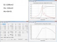
- Mouth at 1200cm2, without dustcap
On 2) the highest amplitude ripple happens at 475Hz. Since this crossover point is going to be active and very steep (like 8th order), and targeted at 400hz, it seems at 475Hz the response is going to be diminished already. The 1667cm2 mouth horn is looking like a good compromise to me. What do you think?
BTW 1667cm2 was chosen arbitrarily, starting with 50cm wife-acceptable width and applying 1.5:1 aspect ratio.😀
My attempt at modelling with the dustcap was just reducing Vtc from 110 to 30cm3. I was surprised to find almost no difference in simulated performance both on frequency response SPL and acoustic impedance. A 0.2dB lowering of the higher end response with 30cm3 vs 110cm3...odd isn't it?
Attachments
Would you happen to have a picture of the driver + dustcap + adapter assembled? I think I could introduce a variation of this concept in my next prototype.
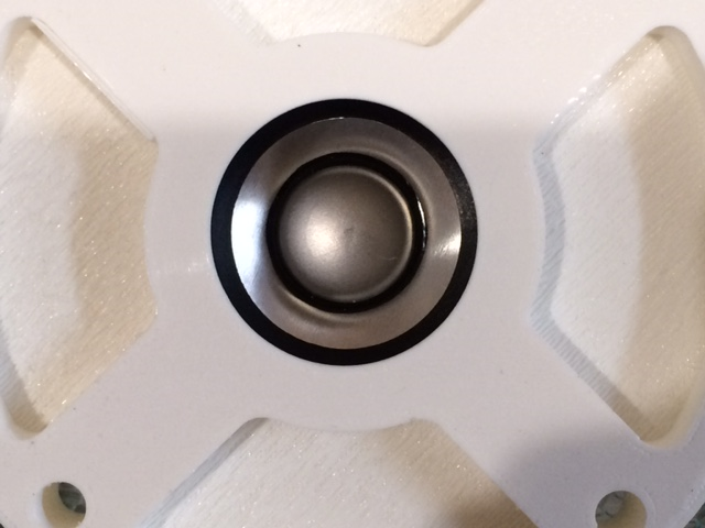
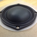
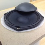
It's hard to get a photo of the cone when it is installed in the horn as it is pretty deep in there. If you look, you will see the silver aluminum cone and a black plastic dustcap.
Here is a photo of the adapter and the FR58EX driver (did not work so well - aluminum dustcap rings too much):
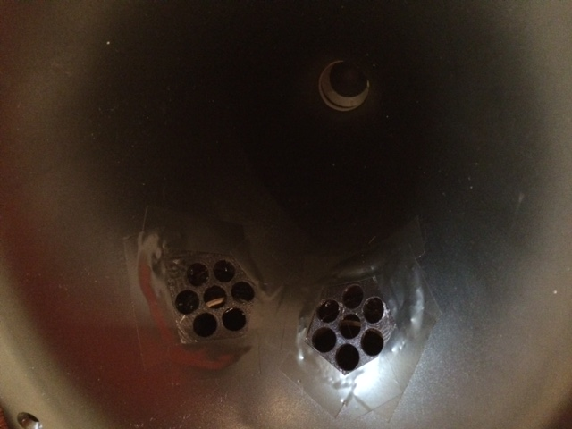
If you look down the bore of horn that Bushmeister made, you can also see the same driver with the black plastic dustcap:
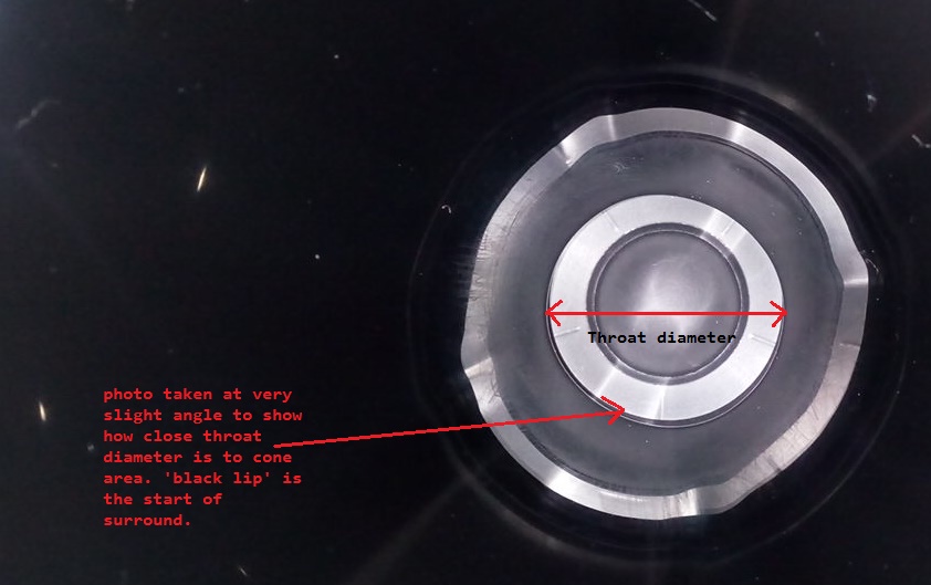
Here is a closeup of Bushmeister's cone and throat adapter:
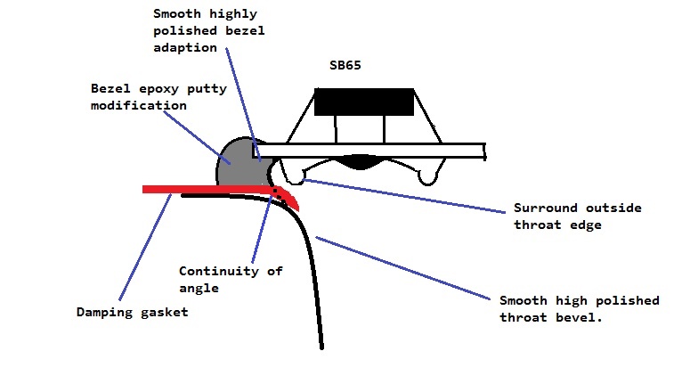
It was really Bushmeister who found that making a smooth adapter provided the smooth response - he did it the old fashioned way using Bondo autobody filler putty and elbow grease. He has a nice diagram of what it should aim to look like here:
All the main details and build notes are here:
http://www.diyaudio.com/forums/mult...ti-way-point-source-horn-125.html#post4644522
Last edited:
Thank you.
I'm having a hard time matching the picture and schematic above. My understanding from the picture is the adapter edge is right at the internal edge of the cone surround. And the picture notes how close the adapter is to the cone, so somehow the adapter seems to be wrapping around the surround - like if the adapter had a recessed grove where the sorround fits. Tough to explain in words I guess. How close is the back of the adapter to the cone?
But the schematic shows the adapter finishing on the outside edge of the surround, hence contradicting what I said above. Could you please explain?
And the adapter also introduces compression and later expansion starts at the horn, right?
I've moved along with the takeaways I got from this thread. One of them was to add a dustcap to the M5N12. I've got a hold of 4" dustcaps that seem to fit perfectly well.
Any advise as to how to attach them? Regular vinyl glue ok? Is it ok for the duscap to be attached at the very edge of the woofer surround? Or should I trim the duscap a bit so it rests on the cone itself?
I'm also building another horn prototype with what I learnt here. Hopefully tomorrow I will be able to share where I'm at.
Attachments
See if you can get your hands on some Loctite Black Max rubber modified cyanoacrylate adhesive. You want a flexible adhesive for this connection.
See if you can get your hands on some Loctite Black Max rubber modified cyanoacrylate adhesive. You want a flexible adhesive for this connection.
Keeping in mind this is still a trial, wouldn't Loctite be basically a permanent adhesive?
I was thinking an easily undoable adhesive would be more appropriate to see how the dustcap performs. If it doesn't work then I still want to have a working driver. If it does work I can implement Loctite. I will look for Black Max. Thanks for the tip!
If you want something to use just for a trial get some old fashioned rubber cement, then you can take it apart and clean it off. It was used often many decades ago to glue paper together.
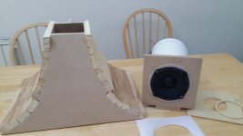
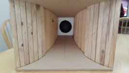
Here's an update of where I'm at, after the feedback I received here.
I'm building a smaller mouth horn (S2=1200cm2 vs 1990cm2 before), 1:1.5 instead of 1:2 before, and S1=Sd (before it was smaller). As before, fc=200Hz.
Stilll work in progress.
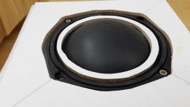
The other prong is regarding the chamber volume and throat. JLH recommended to add a dustcap, and I have the 4" dustcap I mentioned yesterday.
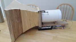
Attached some pictures of how I plan to implement it, for feedback.
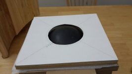
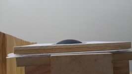
I don't have proper tools, so used a jigsaw to cut the throat opening at 45°, 90mm diameter (3.5"). Not pretty! 😱
The white ring you see placed on top of the cone surround is to be glued to the top plate (throat) so to further reduce the chamber volume.
I guess after doing this S1 is not equal to Sd anymore and I should re-run the simulation.
Looking forward to your feedback!
I'm building a smaller mouth horn (S2=1200cm2 vs 1990cm2 before), 1:1.5 instead of 1:2 before, and S1=Sd (before it was smaller). As before, fc=200Hz.
Stilll work in progress.
The other prong is regarding the chamber volume and throat. JLH recommended to add a dustcap, and I have the 4" dustcap I mentioned yesterday.
Attached some pictures of how I plan to implement it, for feedback.
I don't have proper tools, so used a jigsaw to cut the throat opening at 45°, 90mm diameter (3.5"). Not pretty! 😱
The white ring you see placed on top of the cone surround is to be glued to the top plate (throat) so to further reduce the chamber volume.
I guess after doing this S1 is not equal to Sd anymore and I should re-run the simulation.
Looking forward to your feedback!
Attachments
Progress is good. A couple of things don't quite look ideal to me but more importantly how does it sound?
Progress is good. A couple of things don't quite look ideal to me but more importantly how does it sound?
What are the things that don't look quite ideal? I don't know how it sounds yet as I haven't asembled it yet. I was asking for feedback before doing so, so to minimize mistakes.
And the horn itself still needs a lot of work.
But I'm interested in feedback.
I'm thinking adding the mass of that dustcap will lower the mass rolloff frequency.
So am I. But this was recommended by JLH, who is very knowledgeable, so it's a leap of faith on my part. Yet I don't want to make the mod a permanent one until I can try it.
The expansion at the throat after the baffle around the dustcap. I don't know what effect this is going to have on the extreme high end of the band. Thinking of the geometry, I'm unsure that the dustcap benefit will be fully realised.
My justification for this thinking is, one quality of the primary horn mode is that the wavefront travel straight and true through the horn (if possible).
My justification for this thinking is, one quality of the primary horn mode is that the wavefront travel straight and true through the horn (if possible).
It's unclear whether the bump halfway toward the mouth is indicative that you will be filling back toward the throat in the future, I suppose I should have asked this first.
I asked David McBean about how to properly model the dustcap assembly on Hornresp, included the same pictures as above, and this is what he replied:
Now I'm confused whether the dustcap is a good idea. Maybe my explanation to David was not clear?
Am I on a good track with the dustcap?
Hi LewinskiH01,
Not sure about the S1, Vtc and Atc values.
Don't use the 4" dustcap.
The horn throat area appears to be larger than the driver diaphragm area. This is not good practice in a midrange horn as it results in a significant discontinuity at the throat.
Kind regards,
David
Now I'm confused whether the dustcap is a good idea. Maybe my explanation to David was not clear?
Am I on a good track with the dustcap?
It's unclear whether the bump halfway toward the mouth is indicative that you will be filling back toward the throat in the future, I suppose I should have asked this first.
You are dead on right!
I refrained from getting into all of that because I didn't want to overload people with data, but I guess experienced folks see beyond that 😱
My plan is to start the throat with a circular cross-section at the mouth and transition to a rectangle with rounded corners along the axis, until getting to about 2/3 of the horn length. From there on it will be a regular rectangular cross-section.
Total axial length is 34cm. From 1cm to 23cm there will be the rounded rectangular cross section. The bump you see is at 24cm.
The rounded rectangular cross-section is such that the area is equal to the axisymmetrical cross-section at the given axial point. I solve for the rounding radius that matches both areas. I'll try working with plaster or cement to mold the roundings. The thinking is a smooth transition should help with the higher frequencies in the range, and by 2/3 of the length I'm guessing the expansion has a smaller impact on the higher end as the driver is shifting towards beaming. One issue with the foam prototype was low output above 2kHz.
Having done the excercise I noticed this mistake: all calculations start with an S1=Sd=94.2cm2 which equals 11cm diameter, but the white plate assembly has a 9cm diameter opening to accomodate the dustcap. So there will be an abrupt 1cm step from white plate to the horn itself...can't be good.
I need to go back to Hornresp and use a 9cm diameter mouth. But how should I model the dustcap??
I asked David McBean about how to properly model the dustcap assembly on Hornresp, included the same pictures as above, and this is what he replied:
Now I'm confused whether the dustcap is a good idea. Maybe my explanation to David was not clear?
Am I on a good track with the dustcap?
I assume he means all the space around the dust cap in the throat isn't a good idea and that throat diameter needs to be reduced?
My musings would be on two fronts here. Firstly 1cm is not a quarter wavelength until 8k or so.So there will be an abrupt 1cm step from white plate to the horn itself...
Secondly, tweeter horns can respond negatively to discontinuities down to 1mm, and you are a decade below this, suggesting 1cm can't be too bad.
However the nature of this discontinuity hits the wavefront all at once. 1cm may not be worth worrying about elsewhere in a mid horn, but perhaps not there, not like that, so your intention to fill is reasonable IMO.
Although there seems to be some discrepancy on how to do this I might suggest a thought. Imagine a round flat disc shaped diaphragm, ignoring the suspension and attach it to a horn that best accepts a plane wavefront and has a throat the size of the diaphragm. Many aspects of this would be ideal (from the view of simming it). I've been assuming you're trying to achieve something close to this.But how should I model the dustcap??
- Home
- Loudspeakers
- Multi-Way
- Midrange horn design, cone-driven - 201