The dip at 2k1 (wavelength 16cm) could be the result of a standing wave, at a quarter wavelength from the cone to the rear of the rear chamber. It could also be due to a standing wave from a reflection within the horn.
If a little damping in the rear chamber doesn't change it, try measuring off axis (and not necessarily in only one axis as your horn is not axis-symmetrical)
If a little damping in the rear chamber doesn't change it, try measuring off axis (and not necessarily in only one axis as your horn is not axis-symmetrical)
Hornresp was predicting better performance above 1kHz
The Hornresp prediction is for an axisymmetric horn with the on-axis pressure response calculated at a distance of 1 metre from the horn mouth. The constructed horn has a rectangular cross-section with the on-axis pressure response measured at the horn mouth.
Last edited:
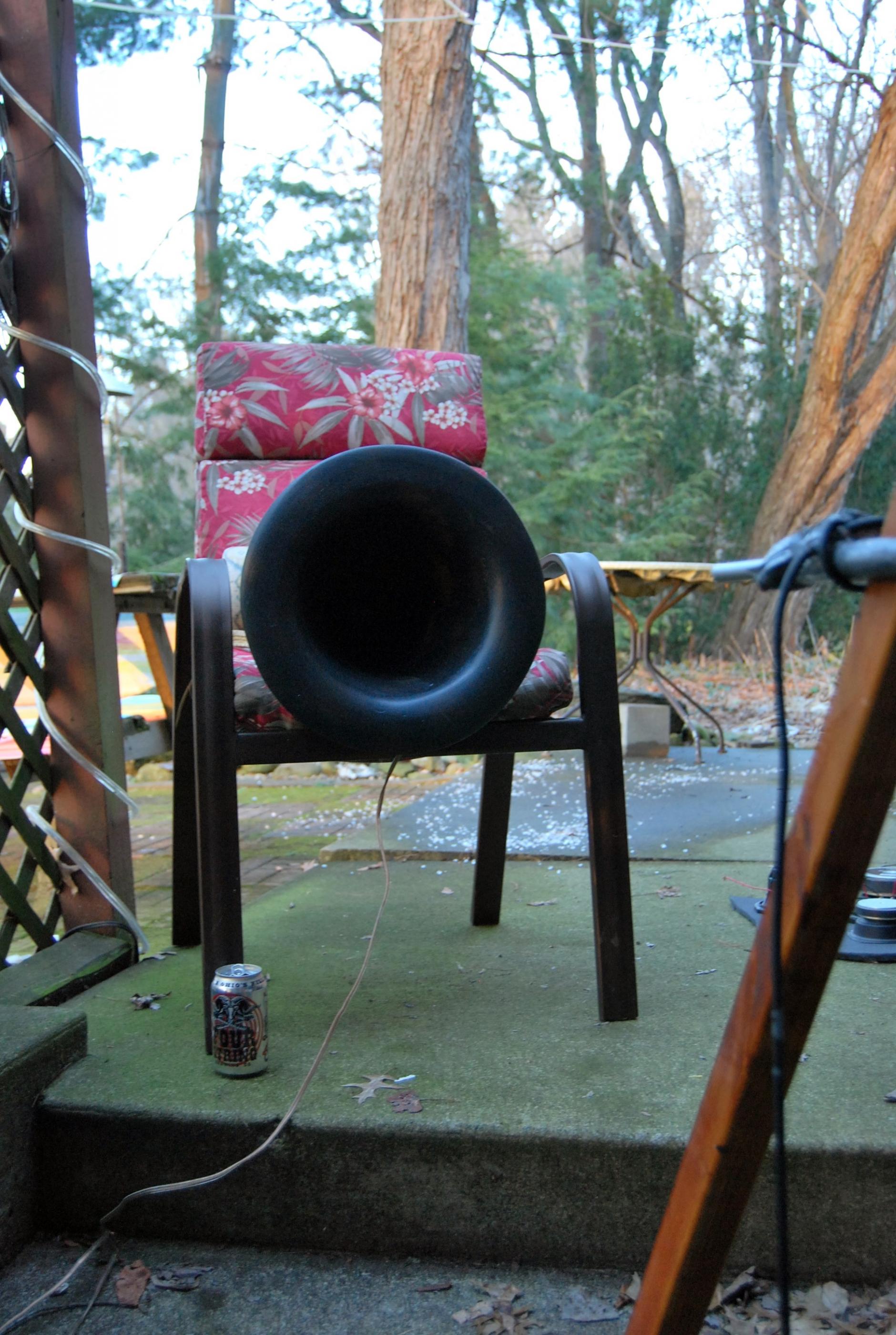
Measure out a meter or more like Mr. McBean posted above. In my experience mid horns are best measured outside and at 2 meters or more. The measurements i see posted here at the mouth are just that and are not really indicative of the practical usable response. At a larger distance the bandwith should even out and extend up further.
The dip at 2k1 (wavelength 16cm) could be the result of a standing wave, at a quarter wavelength from the cone to the rear of the rear chamber. It could also be due to a standing wave from a reflection within the horn.
If a little damping in the rear chamber doesn't change it, try measuring off axis (and not necessarily in only one axis as your horn is not axis-symmetrical)
That's a great observation. The back chamber is longer than 16cm (I'll measure it tonite and come back) and is heavily damped with fiberglass panel. The back chamber is made out of a 6" PVC pipe, though, which is 16cm in diameter so that might be it.
The Hornresp prediction is for an axisymmetric horn with the on-axis pressure response calculated at a distance of 1 metre from the horn mouth. The constructed horn has a rectangular cross-section with the on-axis pressure response measured at the horn mouth.
Hello David, and thanks for joining!
I realize Hornresp assumes an axisymmetrical horn while mine is rectangular. What's your educated guess as to the frequency region where the departure from the assumption becomes more noticeable? Should it be above 1kHz I might need to reconsider if rectangular horns are best for my application.
Measure out a meter or more like Mr. McBean posted above. In my experience mid horns are best measured outside and at 2 meters or more. The measurements i see posted here at the mouth are just that and are not really indicative of the practical usable response. At a larger distance the bandwith should even out and extend up further.
Understood. Will measure tonite 1m away from the mouth. Last night I tried off axis about 15° and basically had the same shape but a couple dB down.
I live in an apartment in a big city, though, so measuring outside is not easily done. Definitely can do that elsewhere during weekends and will do so when I get to fine-tuning, but it's very practical to run a quick measurement, ask for feedback, and remeasure the next day vs waiting to the weekend to remeasure. I'm still in the "getting it directionally right" phase

If measuring 1m away from the mouth, the room will come into play. I will raise the horn to half-room-height (about 1.3m) and centered in the middle of the room width/length wise. Under these conditions, should I continue to measure with FDW @ 10 cycles?
Any additional tips for measuring this?
Re' FDW:
I would say keep reducing the # of cycles and watch the effect. (You don't measure with some number of cycles, you can change that parameter post measurement while looking at the waveform.) If those nulls are due to room effects/reflections at some point they will go away.
I would say keep reducing the # of cycles and watch the effect. (You don't measure with some number of cycles, you can change that parameter post measurement while looking at the waveform.) If those nulls are due to room effects/reflections at some point they will go away.
Any additional tips for measuring this?
I measure my speakers right from the exact spot I will be listening to them at.
It will be interesting to see further measurements. How complicated was that horn to put together ? I only ask because my first inclination (or intuition) is that your throat size is too small. If it were me, I would use a 6x6 inch throat, 250hz flare, 5.75 inches deep, 18 wide, 14 tall
Not too complicated. Can be put together over a week's nights (when I can spend between 0 and 1.5 hs/night).
I tried modelling in Hornresp your suggestion and it didn't work. Meaning I was getting error messages along the lines of "horn is too short", or "mouth can't be larger than X".
Isn't 6"x6" throat large for a 5" driver? And 5.75" length short to load at 250Hz?
I'm probably missing something?
I tried modelling in Hornresp your suggestion and it didn't work. Meaning I was getting error messages along the lines of "horn is too short", or "mouth can't be larger than X".
Isn't 6"x6" throat large for a 5" driver? And 5.75" length short to load at 250Hz?
I'm probably missing something?
I will publicly admit that I know NOTHING about ANY simulators. For me, it's all instinct. With a 250Hz tractrix, we are not interested in getting much lower than ~~~400Hz (or maybe 500?) response. Larger throat= less distortion & less gain. You don't need a heck of a lot more efficiency, you are seeking a matching directivity and a slight gain increase. The larger throat will NOT constrict the highs as much. Bingo.
Okay, now let the flames be thrown at me.
Okay, now let the flames be thrown at me.
I like to use as little damping as I can, which is only practical when the maximum travel time within the rear chamber is as small as required. Easy enough to test.The back chamber is made out of a 6" PVC pipe, though, which is 16cm in diameter so that might be it.
I think there is something in this when waveguiding is the goal. Still, there may be an optimal throat size from the point of view of wavefront contouring out of the cone unless a phase plug is used or highs are not required.Larger throat= less distortion & less gain. You don't need a heck of a lot more efficiency, you are seeking a matching directivity and a slight gain increase. The larger throat will NOT constrict the highs as much. Bingo.
Okay, now let the flames be thrown at me.
Just gate it. If you cant get a long enough sample, move the speaker.If measuring 1m away from the mouth, the room will come into play. I will raise the horn to half-room-height (about 1.3m) and centered in the middle of the room width/length wise. Under these conditions, should I continue to measure with FDW @ 10 cycles?
Any additional tips for measuring this?
If a horn reflection is purely axial and measured on axis, it should be fixed with distance but if it is higher order the frequency is likely to change with distance.
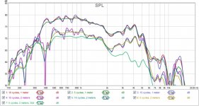
I ran a few measurements tonight: at 1 and 2 meters from the mouth, all on axis, and varying FDW at 5, 10, and 15 cycles.
First graph is an overlay of all. At 2m walls and other reflection points were relatively close and the curve at 2m and 15 cycles shows that - busy line. Even at 1m I think 15 cycles is more confusing than telling.
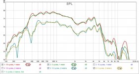
Second graph only overlays measurements at 1 and 2 meters and 5 and 10 cycles.
Like Pooh and David suggested, measuring at 1m does change things significantly. The dip around 2kHz is reduced both at 1 and 2m. Looking much closer to the Hornresp simulation.
Around 400Hz it makes a big difference if measured at 1 or 2m. Likely the room is having a big impact there. Since my midrange will be actively crossed over there and DSP applied, I'm thinking this should be less of an issue. The measurement at 1m does show response very similar to what I was expecting from simulating in Hornresp, in my mind meaning the horn is able to reproduce 400Hz without much effort (it is a 215Hz fc horn).
Would love to get more feedback from experienced eyes. What would you improve?
First graph is an overlay of all. At 2m walls and other reflection points were relatively close and the curve at 2m and 15 cycles shows that - busy line. Even at 1m I think 15 cycles is more confusing than telling.
Second graph only overlays measurements at 1 and 2 meters and 5 and 10 cycles.
Like Pooh and David suggested, measuring at 1m does change things significantly. The dip around 2kHz is reduced both at 1 and 2m. Looking much closer to the Hornresp simulation.
Around 400Hz it makes a big difference if measured at 1 or 2m. Likely the room is having a big impact there. Since my midrange will be actively crossed over there and DSP applied, I'm thinking this should be less of an issue. The measurement at 1m does show response very similar to what I was expecting from simulating in Hornresp, in my mind meaning the horn is able to reproduce 400Hz without much effort (it is a 215Hz fc horn).
Would love to get more feedback from experienced eyes. What would you improve?
Attachments
I will publicly admit that I know NOTHING about ANY simulators.
hey Scott. Instinct is great, especially when supported with experience, like in your case. I guess as an engineer I was trained to think through designs and simulate them before building, which is economically efficient when one does not know what he's doing - like in my case
") That is why I tried to simulate with your input, but Hornresp didn't like it. It seems 250Hz fc and 5.75" long horn don't match.
That is why I tried to simulate with your input, but Hornresp didn't like it. It seems 250Hz fc and 5.75" long horn don't match.Point taken about not constricting highs with a reduced throat.
I like to use as little damping as I can, which is only practical when the maximum travel time within the rear chamber is as small as required. Easy enough to test.
Sure enough, the 6" diameter pipe is 6.1" deep...making this a good suspect for the dip at 2kHz.
FWIW, my plan around the back chamber was derived from a couple posts by JLH, who suggested making a bigger chamber and later filling it in with a closed-cell foaming agent that can be cut when hardened. So the idea is to measure impedance and cut pieces until the impedance peak gets to where you want it. I haven't yet done this, though
Any thoughts as to how to arrive at this optimal throat size? I played around with Hornresp to arrive at the one I'm using.Still, there may be an optimal throat size from the point of view of wavefront contouring out of the cone unless a phase plug is used or highs are not required.
Occasionally I have found even the tiniest gasket imperfection or bolt torquing issue can throw an impedance plot by the better part of an order of magnitude on some horns. The throat also needs to handle more pressure than the mouth, so I guess accuracy is just what I'm thinking at this point. Anyhow, if both channels measure the same and you get a fair tractrix looking impedance plot then give it a try. Soft closed cell foam (excercise mats for example) can be handy for temporary testing if you need to keep it adjustable.So the idea is to measure impedance and cut pieces until the impedance peak gets to where you want it. I haven't yet done this, though
Often a 2:1 throat to sd ratio delays the cone edge radiation enough to leave closer to a dome of spherical radiation. Radiation from the concave cone may work itself out somewhat over the fullness of the horn but at higher frequencies you might just be looking at higher order modes.Any thoughts as to how to arrive at this optimal throat size? I played around with Hornresp to arrive at the one I'm using.
My thought would be to stack more panels inside the top and bottom walls to overlap the cone and see if it changes the issue. Maybe filling in the corners would have an effect?
What's your educated guess as to the frequency region where the departure from the assumption becomes more noticeable?
In this case, your guess is as good as mine
.hey Scott. Instinct is great, especially when supported with experience, like in your case. I guess as an engineer I was trained to think through designs and simulate them before building, which is economically efficient when one does not know what he's doing - like in my case
Point taken about not constricting highs with a reduced throat.
I apologize for not being more clear. The 5.75 inch length corresponds to response possible as low as between 400-500Hz. The FLARE was 250Hz. For Fc of 250hz, you are looking at a length in the neighborhood of 13.5 inches.
As to the back chamber; as per Bruce Edgar's "experience", I would have to agree that no sealed back is worth a try. Short tunnel, filled with acoustic? YES, but no "end cap".
same driver asymmetric horn no back chamber - the dip is there
http://www.diyaudio.com/forums/attachments/multi-way/534278-cone-midrange-horn-101-faital5.jpg
http://www.diyaudio.com/forums/attachments/multi-way/534278-cone-midrange-horn-101-faital5.jpg
same driver asymmetric horn no back chamber - the dip is there
http://www.diyaudio.com/forums/attachments/multi-way/534278-cone-midrange-horn-101-faital5.jpg
Did you mean asymmetric or axisymmetric? I thought that measurement was from this horn http://www.diyaudio.com/forums/atta...72d1456616900-cone-midrange-horn-101-horn.jpg
The dip in your horn seems to be less significant than in mine. And the manufacturer's curves show a little something going on around 2.5kHz (but nothing on the impedance curve), but of low significance too. I'm leaning towards concluding what's happening around 2kHz are artifacts of my implementation: the horn geometry and/or back chamber.
Some next steps coming to mind:
- Tweak edges closest to the driver. Like a 45° chamfer, cut out the vertical edges in front of the driver. Not sure if this will make a difference as the wavelengths around 2kHz are far larger than these dimensions, but maybe diffraction is involved. Dunno. Doesn't hurt trying, and doesn't take much time.
- Measure with back chamber as-is, back cover off keeping the fiberglass (per ScottL's), back cover and fiberglass off (open back, but keeping the pipe since it's bonded to the plate)
- Round the angles between walls of the horn, especially closest to the driver. Using a filler and transitioning from a circular crosss-section at the driver to the horn as-is maybe 10-15cm out.
- Home
- Loudspeakers
- Multi-Way
- Midrange horn design, cone-driven - 201