😍 Those are beautifully milled heatsink and massive! 4 pieces for one BA1?
Will you be kind enough to share with us the fruit of your labour? The Iq that you used and the temperature with these massive heatsinks.
Does the heat spread evenly to the whole heatsink?
as I'm informed, you'll wait some significant time to read about finished amp
as Igor is building it by himself, without hurry, and all aluminium pieces yet need to go to anodizing .......

At 1.85A and +-25 VCC each transistor will be dissipating around 33W?
it's 24Vdc nominal
resulting from usual 18Vac secondaries, with usual CRC filtering, expect 22V5dc rails
so, 22V5*1A8=40.5W of heat per transistor
deliberatelly in format of majority of FW amps, so 4U/400 Modushop Disipante is proper choice
3U/400 if you go down with Iq
2U/400 if you go more down with Iq and if you can squeeze all mechanicals in that height (pcb itself is 78mm tall)
Last edited:

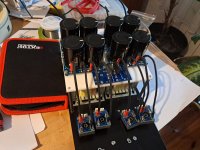
Many thanks😍 Those are beautifully milled heatsink and massive! 4 pieces for one BA1?
Will you be kind enough to share with us the fruit of your labour? The Iq that you used and the temperature with these massive heatsinks.
Does the heat spread evenly to the whole heatsink?
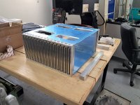
Sure, I will share complete assembling process. It will not be representative, probably too excessive and un-necessary complex and expensive but...I'm not planning to build so many more amps, lets say this one is penultimate 😏
Heatsinks dimensions are 30x200x400 mm. Weight aprx 4.5 kg each. One per side. I hope they are enough to cool transistors. Starting bias will be 1.7A. If all is good, I will keep it. Power is not an issue, I don't need more that 10 watts for Tannoys...so, in case of thermal issues, Zen will help me to determine the right bias
Concerning heat spreading...another good and valid question for which I still don't have the answer. Empirically will be determined do I need to add copper slab or not. Hope this will work as I originally planned.
Attachments

lets say this one is penultimate 😏
oh yeah
that one is soooooo familiar........

... Krell KSA 50 ...
What's this you say? You doing BF-KSA50 next? Can't wait!!! 🙂
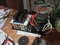
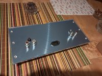
So, small progress...I forgot switch on the back 😛 That and painting are next steps. Heatsinks will be anodized, maybe the rest of the chassis too...
Fun fact: in the spirit of original A1, I decided to add a piece of allu which will transmit part of the heat from heatsinks to the top. Like an L-section...I consider that only warm top amp can be qualified as decent A1 successor 🤣
Fun fact: in the spirit of original A1, I decided to add a piece of allu which will transmit part of the heat from heatsinks to the top. Like an L-section...I consider that only warm top amp can be qualified as decent A1 successor 🤣
Attachments
Output transistors: locally I found small stash of Sankens, 2SA1215 and 2SC 2921. Seller told they are 100% genuine. Well, I'm really not qualified nor equipped to test them other than measure the weight (old topic here as well)
In any case, it's easy when ZenMod is so close, what ever mistake or stupidity I do, he will correct it 😎
In any case, it's easy when ZenMod is so close, what ever mistake or stupidity I do, he will correct it 😎
Attachments

Mighty Zen Mod,
How agnostic is this design to the semiconductors and other minor tweaking?
Output transistors - I have many NJW0281 & NJM0302 from Stasis project, would any changes be required to use them?
Mosfet - will anything similar in TO-220 work and be happy? 520/9520, 3N30/3P20, K2013/J313 ?
Film bypass caps - C6 C14 C15 C24 C25 all appear to be bypass capacitors across electrolytic, do they really need to be 1uF? There are many 0.1uF poly in my collection, but few 1uF with that form factor...
outputs - modern ones are having great gain linearity, so that's main thing; though, to be 158% sure of ending where I did - run THD Spectra test afterwards and - if you have same as I end with, you're good; if off, all you need is to edit value of one base resistor, to lean appropriate, to spoil gain symmetry  - that's what Pa taught us ...
in short - these are good, only dilemma can be - are they having same Hfe ratio N to P as with fancy ones I chose ..... I'm preparing small stickers showing "WESTERN ELECTRIC MADE IN 1943" to stick on them
mosfets - if you use 520/9520 you're close enough so no change of any other parts; rest of noted are having different Ugs, so edit of level shifting resistors is a must; I'm not exxpecting to see any worthwhile change if using Toshibas there... so leave them for something more appropriate, or just send them to OPLDF; in fact, just send them to OPLDF
byppasssssessssss - 100nF is for Sissies; do not skimp on bypass values, or just don't bother with them
assemble without them if you're eager and in hurry, then when you have next mou/digi delivery, put them in
what's with (42) - singing, or not?
- that's what Pa taught us ... in short - these are good, only dilemma can be - are they having same Hfe ratio N to P as with fancy ones I chose ..... I'm preparing small stickers showing "WESTERN ELECTRIC MADE IN 1943" to stick on them
mosfets - if you use 520/9520 you're close enough so no change of any other parts; rest of noted are having different Ugs, so edit of level shifting resistors is a must; I'm not exxpecting to see any worthwhile change if using Toshibas there... so leave them for something more appropriate, or just send them to OPLDF; in fact, just send them to OPLDF
byppasssssessssss - 100nF is for Sissies; do not skimp on bypass values, or just don't bother with them
assemble without them if you're eager and in hurry, then when you have next mou/digi delivery, put them in
what's with (42) - singing, or not?
😆😆I'm preparing small stickers showing "WESTERN ELECTRIC MADE IN 1943" to stick on them
I have the honor of getting my greedy boy hands on some boards to try out, this is as fas as I could get from stock before my DigiKey order arrives.
Really looking forward to this one!

Really looking forward to this one!
- Home
- Amplifiers
- Pass Labs
- MF A1, Kudos to Tim de Paravicini, Ode to my Youth, Babelfishing