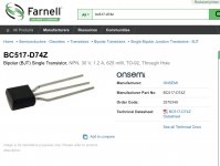
For BC517 the base voltage 0.6V is surely wrong because it's a Darlington. Should have been twice as much at least.
Well a BC517 is installed, so must either be faulty, or does the slightly low 11.3V output of the currently fitted 7812 affect this voltage too?
Have ordered the following spares anyway.
Have ordered the following spares anyway.
Attachments
Not to put the board back after replacing those semis just on hope all relay routes work, I have an idea. While the LM7812 will be out, you could feed external +12V/0 DC to the "note" jumper and to a ground point with crocodile leads. From a battery, some small psu etc. To can debug the whole relays system without the rest of preamp operating. Giving you freedom. No need of sinking the Mosfets & full access to the solder side.but having to take the board out (which is a bit of a pain in my build) I'm going to replace those two as well as the regulator to be thorough.
Don't know, possibly. I have not met 11.3V output from a working LM7812. Such chip regs have an output voltage tolerance spec but not allowing that low.Well a BC517 is installed, so must either be faulty, or does the slightly low 11.3V output of the currently fitted 7812 affect this voltage too?
Have ordered the following spares anyway.
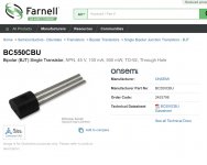
Where 11.3V is to be expected is across the relay's coil (same as across the fly-back diode) because 0.7V VCE is stolen by the driving Darlington. 12V relays have 9V must operate threshold though. BC550CTA is what we usually had for the other transistor. You can also get those instead of CBU if stocked, not to wait. Whatever is stocked. Only difference is in how their leads are formed.
Hello Salas.
I am buying transformer.
50VA 15v x2 have recommended but wall tap is 100V in my country.
Do you recommend 50VA 18v x2 instead?
I am buying transformer.
50VA 15v x2 have recommended but wall tap is 100V in my country.
Do you recommend 50VA 18v x2 instead?
Theoretically yes. But ask a local transformers supplier what type gives 15V+15V secondaries in your country. To be sure.
Not to put the board back after replacing those semis just on hope all relay routes work, I have an idea. While the LM7812 will be out, you could feed external +12V/0 DC to the "note" jumper and to a ground point with crocodile leads. From a battery, some small psu etc. To can debug the whole relays system without the rest of preamp operating. Giving you freedom. No need of sinking the Mosfets & full access to the solder side.
Great idea, thanks! 🙂 I’ve got a 12V psu from an old laptop so could use that for the testing phase befre putting the board back.
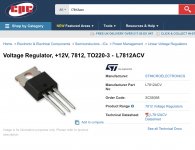
I’ll start by just replacing the reg, as that 11.3V output is outside the usual 2% tolerance spec. I cannot see how it might have been damaged, so perhaps it was one that got through QC testing when it should have been rejected. It’s an ST brand which are usually reliable.Don't know, possibly. I have not met 11.3V output from a working LM7812. Such chip regs have an output voltage tolerance spec but not allowing that low.
Where 11.3V is to be expected is across the relay's coil (same as across the fly-back diode) because 0.7V VCE is stolen by the driving Darlington. 12V relays have 9V must operate threshold though. BC550CTA is what we usually had for the other transistor. You can also get those instead of CBU if stocked, not to wait. Whatever is stocked. Only difference is in how their leads are formed.
Is that output measured with the red probe on pin 3 and black probe on pin 2 GND?
*Pull it out but don't replace it before the 12V external PSU aided debugging. Not to have a bridge back to the rest of preamp during that.
*Pull it out but don't replace it before the 12V external PSU aided debugging. Not to have a bridge back to the rest of preamp during that.
Is that output measured with the red probe on pin 3 and black probe on pin 2 GND?
*Pull it out but don't replace it before the 12V external PSU aided debugging. Not to have a bridge back to the rest of preamp during that.
Black probe was attached to the mounting tab of the reg, which I believe is attached to pin2 internally.
Yes I’ll defintely do this. Just had notification my order has shipped, so hoping I can get going again by midweek.
A reasonable good quality transformer is enough for DCB1 because its line level and no gain. Not very susceptible to a hum field. An R-Core is very nice but not necessary to it for instance. But it would have made a big mains noise interference difference in a phono stage if installed in one same box.Thank you.
I was wondering if I save for cheaper transformer or expensive Japanese made.
Electricity in Japan
Thank you for this. Been away for a while with the Rona. I’m thinking about starting a build soonWorks on a 2014 iMac Retina running OS10.6.8
Is that output measured with the red probe on pin 3 and black probe on pin 2 GND?
*Pull it out but don't replace it before the 12V external PSU aided debugging. Not to have a bridge back to the rest of preamp during that.
Hi Salas.
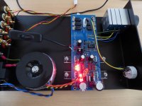
I rigged up a 12V supply, using the power LED ground, and the NOTE area. I stupidly didn't remove the 12V reg first though (and you told me to above!). My fault for doing this whilst tired :/ The LED string on one side lit up. Will I have damaged anything by turning it on briefly like this with any bridge back effects?
Attachments
Last edited:
I wouldn't think you damaged something in the preamp's main circuits with just 12V. You probably energized the plus side shunt reg for a moment. Maybe the 7812 chip reg itself could have sustained a hit because reverse biased. But it is the suspicious one to replace anyway.
I wouldn't think you damaged something in the preamp's main circuits with just 12V. You probably energized the plus side shunt reg for a moment. Maybe the 7812 chip reg itself could have sustained a hit because reverse biased. But it is the suspicious one to replace anyway.
Thanks, that's good to know 🙂 So with the reg. now removed, do I make the same measurements again around the BC550/517 delay area? I noticed the output relay clicking, but again no relay clicks from rotating the input selector switch.
Do those measurements to see if they come closer to my noted voltages so to establish all is well with the output delay and its relay when fed correctly with near 12V after the 7812 reg.
Then go on with debugging the input selection section.
Then go on with debugging the input selection section.
- Home
- Amplifiers
- Pass Labs
- Mezmerize DCB1 Building Thread