Cheers Salas 🙂 Will check all those voltages tomorrow. I’m sure it must be something simple (famous last words!).
Simplest error I would think of is the input number wired for signal vs the selector position assignment is done wrong.
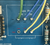
Remember, one side of the board has odd numbered inputs, opposite side has even.
For example in your picture (post #2,572) the source RCAs are connected to input number four.
For example in your picture (post #2,572) the source RCAs are connected to input number four.
Yes I was plugging & unplugging that single wired input into each input socket (and selecting position via jumper cable on the pins rather than using the rotary selector switch) to see if any combination would give me a continuity beep for the inputs up to the pot, but nothing. It seems to be the input relays not doing anything at all, but will look at it with fresh eyes and (coffee allowing) brain tomorrow.
Probably not rekated to any of my issues, but just noticed that R13 and R29 on some Mez pcbs is 1R, but on mine those two are marked as 10R. Should I change mine to 1R Salas?
No big deal, its just a test point resistor to measure ccs current fed to the Leds. You interpret drop across its legs mV/R=mA with a different ratio if 1R or 10R. Wanted to save few mV stolen from Vds on the related Jfet that is why I settled with 1R later on. On the other hand 10R helps with a usual DMM's mV scale resolution. Leave it as is.
Cheers Salas, that’s good to know.
It seems there’s definitely something up with the relay sections on my build.
I’ve unplugged the input and output wiring to exclude that. Using a jumper from selector pin 2 to gnd. Putting a probe on the left or right channel input 2 pin on the pcb, and putting the other probe to the pcb’s volume pot input pad, I get no continuity at all when powered up. So signal is definitely not getting through there.
Even more bizarre on the output side. Putting one probe on either the left or right output pins, and the other on the pots pcb output pads, I get continuity whether powered up or not. It I move the probe to any earth area on the pcb, I get continuity too between that and the output. So seems to point to the relays not doing their thing?
Was trying to avoid it but guess I need to remove the pcb from the chassis now, and inspect the underside again for any possible shorts.
The outputs continuity part to ground when powered off is explainable by the delay relay shorting them to ground for mute.
There is a path to the pot's output pin too but there is series 220R+220R damping resistors +35R JFET RDS in-between.
There is a path to the pot's output pin too but there is series 220R+220R damping resistors +35R JFET RDS in-between.
The outputs continuity part when powered off is explainable by the delay relay shorting them to ground for mute.
It’s the same powered on too.
Don't trust continuity testing that much after the passive input part when powered on. The DMM sends enough DC voltage and it can be trurning on some semi. Alternatively feed 400Hz 1VRMS sinusoidal signal at the pot and trace the path with the scope or with the DMM in AC mode. Can you post close up photos of the input & output relays area?
Don't trust continuity testing that much after the passive input part when powered on. The DMM sends enough DC voltage and it can be trurning on some semi. Alternatively feed 400Hz 1VRMS sinusoidal signal at the pot and trace the path with the scope or with the DMM in AC mode. Can you post close up photos of the input & output relays area?
Sure, I’ll take a couple and post them later. Also going to check the voltages around the BC550 / BC517. I’ve done a little searching and a few relay issues seem to have been caused by bad 550s. So will see what the voltages reveal first. Whilst my soldering skills are extremely neat, unfortunately my fault-finding skills are very basic, so it’d be a relief if it was just an obvious dodgy component.
Haven’t managed to do the voltage measurements around the 7812 area yet, energy levels have been low. But here’s the photo of the input/output area attached. You’ll likely notice the two 220k resistors near the output relay are 330k, as per your suggestion last year for the mix of gear it’ll be used with.
Attachments
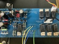

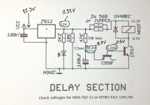
Definitely try a new 7812 regulator. The fact that it doesn't feel hot is fishy too.
Agreed. Have just placed an order for a new ST branded one. Fingers crossed that solves it.
Assume my input voltage of 22.3V into the regulator is as it should be?
Input rail VCC is your raw ps+ The more excess the more dissipation.
Matter of mains and trafo AC level then rectified and filtered. The LM7812 has 35V input spec though. Can handle 22.3V.
Matter of mains and trafo AC level then rectified and filtered. The LM7812 has 35V input spec though. Can handle 22.3V.
Input rail VCC is your raw ps+ The more excess the more dissipation.
Matter of mains and trafo AC level then rectified and filtered. The LM7812 has 35V input spec though. Can handle 22.3V.
Good to know that's all OK then, thanks Salas. Now just to wait patiently until CPC deliver the parts.
I did, yes. But have gone and ordered a new pack of On Semi BC550s and BC517s to replace whatever brands are currently installed, just to make sure. Knowing me I would have ordered exactly what was in the original BOM, so those two parts are probably just fine, but having to take the board out (which is a bit of a pain in my build) I'm going to replace those two as well as the regulator to be thorough.You do use a BC517 coil driver, right?
- Home
- Amplifiers
- Pass Labs
- Mezmerize DCB1 Building Thread