Have measured across the outputs from L --G-- R & have 3.9mV & 4.7mV respectively.
So this is a bit high. Is it possible to bring this down?
Also have measured across the 10R resistors & have 1.6v & 1.8v
Swap the JFETs between them inside each pair of the quad. That should change the results to see if they get better.
Have you got any spare K170 by the way?
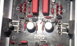
Regarding your negative rail being 0.7V greater than the positive there are two ways to have that difference in a Hypnotize. One is the positive side's bunch of five LEDS to have a lower forward voltage drop (Vf) average or this JFET pointed with an arrow to be much weaker than its counterpart. Or both of those things happening. But that is no problem if the offset fits well the general results. Its then academic like the negative side will clip 0.7V later after the positive if you will drive an almost 20V peak to peak sine wave through to the amp. 7VRMS signal in other words. Most power amps would be already red hot clipping beyond 1-2V RMS signal.
Attachments
The JFET's are matched pairs & put onto the board as per board designations 9240 & 240.
Are you suggesting taking 1 off each 9240 & 240 out & swapping them over ?
No I have no spare K170
Thanks for the help, James
PS.
The Input sensitivity of my power amp is about 600mV so will have to deal with that a bit later.
Are you suggesting taking 1 off each 9240 & 240 out & swapping them over ?
No I have no spare K170
Thanks for the help, James
PS.
The Input sensitivity of my power amp is about 600mV so will have to deal with that a bit later.
Have measured across the outputs from L --G-- R & have 3.9mV & 4.7mV respectively.
So this is a bit high. Is it possible to bring this down?
Also have measured across the 10R resistors & have 1.6v & 1.8v
The jFETs can't be matched pairs with those output offsets.The JFET's are matched pairs & put onto the board as per board designations 9240 & 240.
Are you suggesting taking 1 off each 9240 & 240 out & swapping them over ?
No I have no spare K170
Thanks for the help, James
PS.
The Input sensitivity of my power amp is about 600mV so will have to deal with that a bit later.
I suspect you have mixed them up or they were never selected by your supplier.
Salas seems to think similar.
Salas, I will swap the JFET's as you suggest. One pair at a time to see if voltages start to line up.
As I have to unbolt the heat sinks from the MOSFETS & the chassis in order to swap the JFETs it'll be tomorrow evening before I can get back to you regarding this.
Will it ok to power the board up to check the output for a short while without the heatsinks ?
Andrew, I was careful to make sure the MOSFETS (it was these that were supposed to be matched) were put in correctly but I will check them to make sure.
James
Last edited:
Will it ok to power the board up to check the output for a short while without the heatsinks ?
Maybe for very short intervals then let cool. Don't let them 9240 & 240 go 100C on their body, it will be near destruction limit in the much hotter silicon core inside. Its about 5W dissipation for each MOSFET in your build right now. Not little at all for a non assisted power part no matter if chunky looking.
The jFETs can't be matched pairs with those output offsets.
I suspect you have mixed them up or they were never selected by your supplier.
Salas seems to think similar.
The jFETs should be selected to have very similar Idss.Salas, I will swap the JFET's as you suggest. One pair at a time to see if voltages start to line up.
As I have to unbolt the heat sinks from the MOSFETS & the chassis in order to swap the JFETs it'll be tomorrow evening before I can get back to you regarding this.
Will it ok to power the board up to check the output for a short while without the heatsinks ?
Andrew, I was careful to make sure the MOSFETS (it was these that were supposed to be matched) were put in correctly but I will check them to make sure.
James
The mosFETs don't need matching/selecting.
The mosFETs are all correctly mounted.
"would love to know just what Idss is & how it's measured"
Can the Idss be measured with the 170 in situ ?
"would love to know just what Idss is & how it's measured"
Can the Idss be measured with the 170 in situ ?
Not when placed in full circuit. 2SK170 matching"would love to know just what Idss is & how it's measured"
Can the Idss be measured with the 170 in situ ?
"Get a 5 to 13 volt supply and a DC voltmeter. Connect the +V to the
Drain, connect the Gate and Source together to a 100 ohm resistor,
and connect the other lead of the resistor to ground.
Measure the voltage across the resistor, which gives the Idss. 1 volt
= 10 mA of current."
wish I knew what this meant as I only understand a part of it...thats the first sentence get a battery & a voltmeter!! the rest is beyond me.
It would seem that getting hold of matched JFets is not so easy unless one orders from the US & pays an exorbitant postage fee.
Can't find any matched from the UK.
It might well be that just de-soldering them might well destroy them.
Anyone on this forum have some leftover? As it also seems that one has to by lots & sort them with the right kind of circuit to test them.
Last edited:
When you don't completely understand the above and you are not confident about rework experiments better leave it well alone before some parts accident happens.
Your build's offset is not stellar but still in the acceptable zone as it is. If your power amp has an input capacitor (AC coupled) then it is a non issue altogether. If not (DC coupled) and it has say twenty times voltage gain (or 26dB) then a four mV input offset adds 80mV contribution to its own output offset. Still acceptable DC at speaker level. Not best but not dangerous.
If you want to have a possibly better matched JFET quad to try at some point or for spares since they are NOS (new old stock), thus due to extinction sooner or later, there is Spencer of FetAudio.com from HK and Alweit of AudioFET from Israel on Ebay that sell reliable 2SK170BL matched quads for IDSS on a very moderate postage fee.
Thanks for the information on getting the 2SK170BL.
As the Hypnotise is in the "Acceptable Zone" Ill leave well alone till such time as Matched JFETs can be obtained.
One last question regarding My Power amp, It is a Leak ST20 Valve amp, Do you know if this would this be AC coupled or DC coupled ?
As the Hypnotise is in the "Acceptable Zone" Ill leave well alone till such time as Matched JFETs can be obtained.
One last question regarding My Power amp, It is a Leak ST20 Valve amp, Do you know if this would this be AC coupled or DC coupled ?
Not AC coupled on its input, later on. But 4mV offset is like a mosquito to a pig difference regarding the Leak's 1.5V input valve's cathode voltage bias. Then it has two inter-stage AC couplings.
Any valve amp with an output transformer like yours can't have or pass any output DC offset anyway because there is no path to conduct it. The output stage is AC coupled to the speakers via electromagnetism.
In other words just hook up your DCB1 build to it and enjoy music. No worries. Let us know how you liked it.
Thanks Salas, thats very reassuring for me to be able to now carry on.
"like a mosquito to a pig difference"' 😎
The build is now at the stage of cabinet/box construction so it will be a little while, but yes I will let you know.
Thanks for you time & help
"like a mosquito to a pig difference"' 😎
The build is now at the stage of cabinet/box construction so it will be a little while, but yes I will let you know.
Thanks for you time & help
Last edited:
The 2SK170BL seem to come in matched Quads with an Idss of +/- 0.3mA or +/- 3%
Which might be best for the Hypnotise or are they the same?
Which might be best for the Hypnotise or are they the same?
I am about to finish my build and have the following quick question.
I use the blue Mezmerize pcb from diyaudio store. For the two 10ohm next to the test points and the 100uF caps, it is noted that the Hypno version specifies the values as 1ohm. Does it matter to use 1ohm or 10ohm?
Thanks!
I use the blue Mezmerize pcb from diyaudio store. For the two 10ohm next to the test points and the 100uF caps, it is noted that the Hypno version specifies the values as 1ohm. Does it matter to use 1ohm or 10ohm?
Thanks!
Not matter. Its just a test point for measuring mV that can translate to mA info. Some would use early DCB1s as PSU only for other stuff so by knowing that they could estimate changing Vref parts for different voltages. That was its main purpose and for servicing info.
- Home
- Amplifiers
- Pass Labs
- Mezmerize DCB1 Building Thread