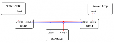
Right now my dcb1 are in 2 different casing. Or perhaps I can run them as mono? Each driving a mono amp?
You can probably parallel the available channels for double the driving current availability and half the output impedance
You can probably parallel the available channels for double the driving current availability and half the output impedance
I am not sure how to translate your explanation into a diagram.
I am not sure how to translate your explanation into a diagram.
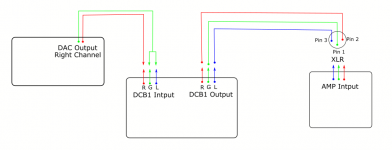
Well, parallel is simply parallel. Feeding input signal from a source's one channel to both DCB1 channels and driving an amp's one channel from both the dcb1 channels outputs. Talking SE. For bridged balanced I showed with the two channel XLRs wiring schematic.
Couple more questions.
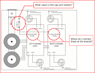
10R 0.1uF
To the PSUs outputs middle zero pads (at the area you note the rails Voltages results in your troubleshooting pictures)
The Main Audio Ground (MAG) to Chassis connection (as shown) is not able to pass Fault Current in the event of a mains failure incident.10R 0.1uF
To the PSUs outputs middle zero pads (at the area you note the rails Voltages results in your troubleshooting pictures)
I also recommend that the two connections be made separately to the Chassis. Either direct wire connection, or via a Disconnecting Network that is rated to pass Fault Current.
If the two separate DCB1 need an audio connection, then make that separately to maximise the audio performance, not via the Safety connection.
Last edited:
Hi to all, I have managed to populate the majority of the board except for the 4 x matched k170BL, I have powered the powered the board with a 12 CT transformer I had at hand, and I am getting the following voltages:
- over the positive (9240 MOSFET) side 3 LED's I have 5.42V ;
- over the negative (240 MOSFET) side 3 LED's I have 5.44V ;
- on the positive side 5 LED's I have 8.90V and on the negative 8.84V (Here I could play with one or two LED that I have measured with 100mV higher the the red ones to get close to 9V)
- on the test point, the output of the reg. (the 3 little pads behind the 10ohm resistors ) I have 9.52V on the positive side and 9.48V on the negative.
Picture :
All LED'S are working fine as seen in the picture, nothing is overheating, I have used where there was no need for LSK170 replacement with Andrew's help (thanks again ), one thing I noticed is that on the negative side once I cut off power the 3 led's stay on a bit longer, is there an issue?
The relay also clicks after a few second of powering the board also.
Any input from the more experienced members?
Thanks,
Florin
- over the positive (9240 MOSFET) side 3 LED's I have 5.42V ;
- over the negative (240 MOSFET) side 3 LED's I have 5.44V ;
- on the positive side 5 LED's I have 8.90V and on the negative 8.84V (Here I could play with one or two LED that I have measured with 100mV higher the the red ones to get close to 9V)
- on the test point, the output of the reg. (the 3 little pads behind the 10ohm resistors ) I have 9.52V on the positive side and 9.48V on the negative.
Picture :
An externally hosted image should be here but it was not working when we last tested it.
All LED'S are working fine as seen in the picture, nothing is overheating, I have used where there was no need for LSK170 replacement with Andrew's help (thanks again ), one thing I noticed is that on the negative side once I cut off power the 3 led's stay on a bit longer, is there an issue?
The relay also clicks after a few second of powering the board also.
Any input from the more experienced members?
Thanks,
Florin
To click later on is normal because its a time delay signal connection circuit. To avoid passing a power on DC offset bump or other transient. But it disengages fast at power off.
The negative side's Leds staying a bit longer lit at power off is also normal. The positive side's reservoir capacitor drains out a bit faster because it has to feed the relays and their support circuits too.
The measured voltages are good enough for matching and near enough to nominal.
The negative side's Leds staying a bit longer lit at power off is also normal. The positive side's reservoir capacitor drains out a bit faster because it has to feed the relays and their support circuits too.
The measured voltages are good enough for matching and near enough to nominal.
Hi Salas, so I should leave it as is or swap some LED s to reach the target 10v as in the schematic? I dont really like desoldering in the LED section because of pads footprint.
No problem, leave them Leds as they are. You are in ballpark rails spec and their matching is also very good.
you have to be using a 24Vac Centre tapped transformer.Hi to all, I have managed to populate the majority of the board except for the 4 x matched k170BL, I have powered the powered the board with a 12 CT transformer I had at hand, and I am getting the following voltages:
- over the positive (9240 MOSFET) side 3 LED's I have 5.42V ;
- over the negative (240 MOSFET) side 3 LED's I have 5.44V ;
- on the positive side 5 LED's I have 8.90V and on the negative 8.84V (Here I could play with one or two LED that I have measured with 100mV higher the the red ones to get close to 9V)
- on the test point, the output of the reg. (the 3 little pads behind the 10ohm resistors ) I have 9.52V on the positive side and 9.48V on the negative.................
You can't get those voltages froma 12Vac CT.
To make allowance for when the mains voltage is low you should use a 30Vac CT or dual 15Vac.
Hi Andrew, yes it is a 24V transf with a center tap (my mistake 🙂 ), so 12-0-12, I have the 15V one also but that one is with double 15v secondaries and to connect to the board I was supposed to join the correct ends correctly, attach separate wires to the enameled ones (two much hassle for a simple test) ......., using the 12v one was the quickest for a test and also I didn't had proper radiators to put on the mosfets for that voltage difference.
Thanks,
Thanks,
Last edited:
A dual winding transformer can be wired incorrectly.
Always use Mains Bulb Tester to ensure your wiring is correct before you blow up an expensive project.
And don't believe the colour codes on the wiring. Test your wiring every time !
Always use Mains Bulb Tester to ensure your wiring is correct before you blow up an expensive project.
And don't believe the colour codes on the wiring. Test your wiring every time !
I have another board without caps that I use to check before I connect to the final "user" , but before connecting it to that test board I use the DMM to test and check how to join the leads, it does have color markings on the outer insulation but just as you say check before use to avoid expensive screw-ups. I have used a couple of this type of transformers before with single bridges dual rail supplies and I had no problems, i prefer ordering the dual secondaries because these are more versatile than the center tap ones.
Anyways if the DCB1 board at least the regulator side is within working limits I am more than happy. I will check today and post the part number of the LED's that I got because these were all very close to 1.8V, so others won't have to buy and test different types and spend extra money if it's not necessary. Also the part number for the relays 🙂 .
Thanks for the input.
Bad luck with LED's
Hi, guys. I posted this over in the Mezmerize B1 Buffer Preamp thread, but am posting here as well because this thread seems to have more subscribers. I'm finally getting around to building my DCB1, and am having trouble with the LED sourcing.
I purchased the 593-VAOL-3HCE4 VCC 1.8V 20mA LED's as per the BOM. I am measuring them using a 9.71VDC battery, and have tried them with both a 1K and 1.5K resistor. I am measuring 1.91V (7.8 mA) with the 1K resistor. I am measuring 1.89V (5.2 mA) with the 1.5K resistor. Earlier, I had checked them with a 460 ohm resistor to get closer to their rated current, and they measured 2.01 V. So, clearly, they are not 1.8 Vf LED's as advertised.
Can these be used? I think not. If not, can I get some part number recommendations from those who have had better luck hitting the 1.8V nominal target. I don't mind waiting a week to get this right.
Thanks,
Andy
1.91V X5 = 9.55V. Add 0.6V Vbe from the transistor at the base of the five LEDs string. That's 10.15V. Its alright. It may even go bit higher than that with random K170BL IDSS and BC5XX Vbe tolerances but rather seldom to go bit less. The K170BL matched quad has absolutely no problem working at lower or higher than 10V symmetric. Its just a subjective SQ rails level target that I approached in DCB1's design which can take enough play when the building parts are not producing spot on 10V.
- Home
- Amplifiers
- Pass Labs
- Mezmerize DCB1 Building Thread