Leds Vf alone is around 2V (green) so you need a higher voltage source to touch them up. Some DMMs diode check gives up to white Led 3.5V, some don't, they give up to 1.5V good only for diodes. To see about diodes touch them up with diode check with power off. To know if your diode check can light an Led try a green from your parts bin with it, else use a 9V battery or two 1.5V oin series for voltage source.
Sorry, those LEDs lights up at 1.8v. 1,5v was too faint i wouldn't see the lights. All LEDs lights up at 1.8v except for one. I'll change that and report back.
Thank you again.
Lets hope its down to just a bad Led then
Okay. I changed the bad LED and the BC550 and now it lights up and I can hear a clicking sound after powering on. But the left side dc offset is running at 11.08mV and 9.00mV and the right is running between 158mV to 128mV. And it keeps going up and down for both channels.
I checked it again and now it starts at 300mV at the right and running down. The left channel starts at 11.00mV and goes down to about 2mV. Then it goes between 2mV and 9mV.
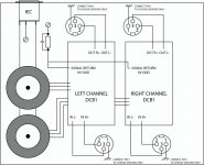
I have actually installed a CL-60 thermistor between the mains 'L' and the transformer. I don't know if this is causing the problem.
I checked it again and now it starts at 300mV at the right and running down. The left channel starts at 11.00mV and goes down to about 2mV. Then it goes between 2mV and 9mV.
I have actually installed a CL-60 thermistor between the mains 'L' and the transformer. I don't know if this is causing the problem.
Last edited:
These are the measurement.
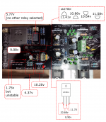
The rail voltage for left is 10.63v and 11.64v for right.
DC offset at right channel is 300mV but going down.
DC offset at left channel is 30mV but going down.
In place of the BC517 is a BC550.
In place of the BC550 is a zener diode at 3V 1W
The zener diode measured at 1.944v
The rail voltage for left is 10.63v and 11.64v for right.
DC offset at right channel is 300mV but going down.
DC offset at left channel is 30mV but going down.
In place of the BC517 is a BC550.
In place of the BC550 is a zener diode at 3V 1W
The zener diode measured at 1.944v
Attachments
Last edited:
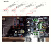
The rails and relay coil voltages are in range now. Not greatly matched but fixed. With the power off, measure each 2SK170 of the audio signal quad with the DMM in Ω mode across Drain & Source. When good they are showing in the range of 50Ω each. There is danger they went too hot when you had +20V -10V rails malfunction. Also connect a pot just in case some open input noise component is passing through.
Hi.
These are the measurement with the power off. 2 are bad. Are the 29.9 ohm still good?
These are the measurement with the power off. 2 are bad. Are the 29.9 ohm still good?
Attachments
Last edited:
29.9 Ω is still good for BL (RDS is less when IDSS is more). Pull them all out, measure IDSS for all, see if the suspicious ones are problematic, see if your original IDSS pair matching still exists.
These are brought matched from Spencer. i don't have their data. At 200k plus ohm it still is good?
No, its not a good sign. Still because the gates can be charged by the DMM and alter the indications pull them out and verify IDSS. For the middle ones there is no worrying sign but you will need to know their IDSS if to ask new ones that match to them. See how in #3 http://www.diyaudio.com/forums/pass-labs/228897-jfet-matching-sorting.html
Put the resistor to the +V drain line where its usually located in this test and check again if it gives the same indications.
Attend to better rails symmetry given the chance. Try to bring the 11.64V rail down by a Volt. Needs the leg trick or it has stronger Vf Leds in average than the other side? Measure the 5 Leds drops individually per side as they are alight. Make changes where needed. Then solder back to the board your two best Idss matching pairs. Connect a pot in the end also.
Attend to better rails symmetry given the chance. Try to bring the 11.64V rail down by a Volt. Needs the leg trick or it has stronger Vf Leds in average than the other side? Measure the 5 Leds drops individually per side as they are alight. Make changes where needed. Then solder back to the board your two best Idss matching pairs. Connect a pot in the end also.
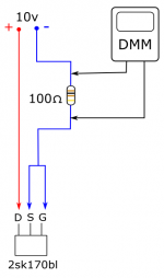
these 4 measurements indicate that the Idss is pretty close and that they are probably undamaged.From NP : a quick way to measure the 2sk170bl ( picture).
I have removed and measured the quad 2sk170bl and the measurement is as follow:
3 pieces is at -0.737v and the other piece is at -0.740v.
That then cannot explain why you are getting major output offset errors.
Maybe there is another damaged area?
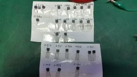
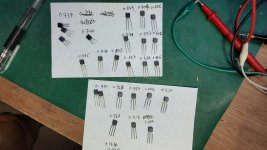
Sorry to say: the 4 desoldered ones look real, rest are fakes.... Look at different printing between the four and the rest.
Sorry to say: the 4 desoldered ones look real, rest are fakes.... Look at different printing between the four and the rest.
The measurement suggest otherwise. These were brought about the same time that I brought the Mesmerize boards, probably around 2008. When I have some time, I'll meausure them up using the 3 points method.
There is possibility that there were in circulation originally diffused in Japan but packaged in Thailand at the time that had this kind of print. I had some K117s like that which traced out correctly. That facility got flooded by some bad weather or otherwise at a point. These days such a chalk like print is almost always a sign of fake stuff.
Now, I have changed all the LEDs on the right side. They have a higher voltage compare to the left side. I have also replaced one of the LED on the left side because it was a bit out of the range.Then I connect the pot and the rest of the inputs and the output. It is good now. The right rail is at 11.02v and the left rail is at 10.50v. DC offset for right is 1.3mV and left is at 0.9mV. I think the reason for the high DC offset previously was due to the unconnected pot and probably also the higher right side voltage. Thank you very much Salas. You have again come to my rescue a second time. Now I have 2 of these DCB1. Is t possible to bridge them?
- Home
- Amplifiers
- Pass Labs
- Mezmerize DCB1 Building Thread