Getting Ready
I am about to start my Mesmerize preamp build and had a couple of questions before I start ordering parts.
-I ordered the PCB from the DIY parts store. I assume I should follow the BOM listed below the PCB using the link on the product page?
-Concerning the listed relays, I only need to use as many relays as I plan on having inputs, correct? I am in the U.S. and typically order my parts from Mouser, the parts listed on the BOM are NLA, what current relays could be be used as replacements?
-What's the difference from using 5V or 12V relays?
-what's the recommended size of transformer? Would a 50VA 2X 12V work? Or should I get something different? Using a dual output transformer, do I twist the middle pair together to fit in the three inputs for power?
-Do I need to use a PSU or do you just wire the transformer straight to the board?
Sorry for all the questions, I would appreciate any input you can provide to help me out as I'm kind of new to DIY.
I plan on using this with a DIY Aleph J and possibly a LM3886 amp.
As many relays as many inputs you need
NEC EA2-12NJ (Mouser has it in stock)
12V ones are less of a burden for the chip regulator in mA and they do not need the extra dropping resistors
50VA 15-0-15 is even better. Yes you create a midpoint if its a four wire double secondary trafo
Straight to the board. DCB1 has its own rectification bridge, reservoirs, shunt regulators, on board.
Great, thanks for the fast reply. I will try and post some pictures as I get going here in the next few weeks.
What is a suitable replacement for the Toshiba 2SK170 BLF as they are no longer in stock?
Thank you
Thank you
Nothing except LSK170 B Grade from Linear Systems that you must find four in matched IDSS also. I haven't seen them offered as such lately. There are two guys on ebay who offer matched quads Toshiba 2SK170BL. Their feedback is 100% and comments say they are genuine. One is from Germany the other is from Israel. Maybe you can ask them for the rest of 2SK170BL too but in random picks since they not need be same IDSS.
Hey guys,
I got mine from Spencer at fetaudio.com. That was after Salas helped me identify some fake ones I'd ordered from what was supposed to be a reliable source.
Hey brookhart995, the DCB1 was my first non-kit project. Thanks to help from Salas and others on this thread I got it done and it sounds great. Just search for "dbis" on this thread and you'll see some of the questions I had. Might help you out. Anyway feel free to ask any questions along the way. I'm still a newbie but I'll try to answer to the best of my ability. Good luck!
BTW, since the Mezmerize, I've built an F5 amp, working on Sony Vfet amp, and I've got Salas's new preamp and folded simplistic phono preamp kits waiting in boxes to be built.
Correct, I forgot to mention Spencer this time. Thanks for mentioning.
You got quite busy with DIY since the Mez I see. That's nice. 🙂
You got quite busy with DIY since the Mez I see. That's nice. 🙂
I will shortly be fitting the Mez board (as It's been Hot Rodded) to the chassis with Heat sinks.
Q; Do I need to insulate the 9240 & 240's from the heat sinks & or the chassis. As their is continuity between the steel back of said 9-240 & it's centre leg.
Q; Do I need to insulate the 9240 & 240's from the heat sinks & or the chassis. As their is continuity between the steel back of said 9-240 & it's centre leg.
Jumpers?
On the mesmerize board there are two white lines. Do I need to jumper those, or leave them alone?
On the mesmerize board there are two white lines. Do I need to jumper those, or leave them alone?
They must be already having copper lines under the white lines. Check that with your DMM's continuity.
Thanks
Salsa, they do already have copper traces on the underside of the board. I guess the white lines are showing that a connection is there. The BOM in the store shows a 100nf and 150nf are needed, but I can only find the location for the 100nf. Has the 150nf been eliminated? Thanks in advance.
Salsa, they do already have copper traces on the underside of the board. I guess the white lines are showing that a connection is there. The BOM in the store shows a 100nf and 150nf are needed, but I can only find the location for the 100nf. Has the 150nf been eliminated? Thanks in advance.
The 150nF was listed for a tentative botch. To be soldered underside across base and collector in case relay chatter occurred if no BC517 Darlington was available and you had to use a simple NPN instead like BC550 as the output relay's coil driver. Especially 5V relays could make such a transistor oscillate and you could hear the contacts chattering. Even then, not always. The 150nF could solve that. If you got the designated BC517 then the chances of chattering are zero as far as never reported here.
It works, However.
Dcb1 is up & running All LED's lit 😀
The voltages at V+ = 9.8 & V- = 10.5
is this ok ?
As the board has been hot rodded with 10R 3% does this mean it's running at 200mV ? how & where do I measure this ?
If I choose to Hot Rod it some more which resistor/s do I change & to what value?
Hears a pic of the board, It will have more space in the final build & probably a bigger heat sink.
Attachments
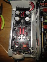
Jay you measure the voltage across the 10R resistors which are also the ones to change to a lower value if you want to further hotrod .
This is a Hypnotize in the picture and it could be doing better rails matching, the Mezmerize is the one designed to self create some rails asymmetry.
Nonetheless critical is the DC offset outcome not the rails values per se. So measure DC mV at the audio outputs. If its low all is well. Up to 5mV is acceptable, up to 3mV is good, up to 2mV is fine, less than 2mV is great.
When you measure the Vdrop across each 10R resistor you know the current by Ohm's law I=V/R. Usually falls somewhere between 150mA and 200mA.
To hot-rod more, you just use lower than 10R current setting value. Say by -2.5R step. But the resistor's own dissipation and the need for Mosfets sinking goes quickly up. Many users agreed that 10R sounds good enough while the temps and sinking are still very manageable.
- Home
- Amplifiers
- Pass Labs
- Mezmerize DCB1 Building Thread