Hi people, I hope someone can help me get on track. It seems the Mezmerize creates a ground loop with my Hiraga amplifier. As soon as I connect the pre to the Hiraga, a hum is present.
There is no offset present on the DCB1, I checked and double checked. So now I'm bald and still hum 🙂
Please help? I am thinking about isolating the output of the DCB1 or the input of the Hiraga. But that will probably result in poor sound quality. So any help on the matter is greatly appreciated!
There is no offset present on the DCB1, I checked and double checked. So now I'm bald and still hum 🙂
Please help? I am thinking about isolating the output of the DCB1 or the input of the Hiraga. But that will probably result in poor sound quality. So any help on the matter is greatly appreciated!
Does the Mez have a hum loop with another amplifier? If not, see what are the differences in how your Hiraga is internally grounded vs the other amplifier.
Hi Salas,
I only have a commercial spare amp whitch probably has all kinds of input caps......
Strange that the amp is dead silent with nothing connected........
I only have a commercial spare amp whitch probably has all kinds of input caps......
Strange that the amp is dead silent with nothing connected........
To theoretically inspect a ground loop it takes we first have a detailed drawing of the grounding scheme for both the pre & power builds.
For a quick practical inspection first see if the Hiraga build has chassis grounding that shows continuity to its PCB signal ground also. If when disconnecting its IEC ground the hum loop stops then it needs a safe ground lift with a bridge rectifier.
For a quick practical inspection first see if the Hiraga build has chassis grounding that shows continuity to its PCB signal ground also. If when disconnecting its IEC ground the hum loop stops then it needs a safe ground lift with a bridge rectifier.
Ok, I'll check that first. Thanks!
Also i read that a 15R resistor can help on the input ground of the amp modules.... I will fiddle around with all that, starting with the grounding / chassis grounding.
Thanks!
Also i read that a 15R resistor can help on the input ground of the amp modules.... I will fiddle around with all that, starting with the grounding / chassis grounding.
Thanks!
That's a loop breaker resistor measure many times effective. Its probable that the answer is in the amp's grounding scheme reformation because there are so many Mez builds around mated with so many different amps and its not a buffer that has been reported as hum prone in general. Given that its not malfunctioning of course.
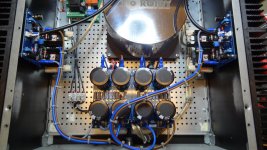

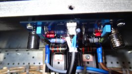
I see signal wires touching the transfo and their shields probably not engaged. Does it also hum when connected to no preamp?
Hi Salas,
They do not touch the trafo. Just looks like it in the picture.
No hum when no pre is connected.
What I I did wrong is not connecting the shield of the signal wiring anywhere.... So the shield has no function now. Thanks for pointing that out.
Things I will do:
-Connect the shield to ground on chassis RCA
-Put 15R resistor on ground in place of the amp boards
-Fix a 1nf ceramic from ground on chassis RCA to chassis, right next to chassis RCA
Let's see what that will do....
I will NEVER take off the earth when live...... That can be a deadly misstake 🙂
Hi All,
I've just powered up my Mez for the first time. The voltages at the test points are +10.27v and -9.61v but none of the string of three LEDs on the + side are lit. All the other LEDs are bright. Has anyone any idea what the problem may be before I pull the PCB out and start checking? Thanks.
I've just powered up my Mez for the first time. The voltages at the test points are +10.27v and -9.61v but none of the string of three LEDs on the + side are lit. All the other LEDs are bright. Has anyone any idea what the problem may be before I pull the PCB out and start checking? Thanks.
Thanks guys. Two LEDs were inserted the wrong way round. I thought that I was being super careful when stuffing the board. Probably the result of working on it too late at night!
Now I've just got to reconnect the board and make the selector switch wiring.
Now I've just got to reconnect the board and make the selector switch wiring.
Hi All,
I'm in the process of populating my Mesmerize board and was stuck at the part of the "NOTE: Replace with jumper if use 12v Relays." I soldered a jumper on one of the slots where the Note is but soldered the Decoupling A (150nF/63v Metal Film Cap - Near BC517). Should both be jumped instead? What's the Decoupling A for? Will be using 12v Relays.
I'm in the process of populating my Mesmerize board and was stuck at the part of the "NOTE: Replace with jumper if use 12v Relays." I soldered a jumper on one of the slots where the Note is but soldered the Decoupling A (150nF/63v Metal Film Cap - Near BC517). Should both be jumped instead? What's the Decoupling A for? Will be using 12v Relays.
The resistor is there to allow a 5V relay to work with a 12V regulator feeding it.
With a 12V regulator and a 12V relay you don't need a resistor. use a link instead.
However, I found that I prefer to use a 15V regulator and then populate with a resistor to reduce the current to ~ 70% of normal 12V current. This makes the relay and the regulator run cooler, less heat inside the case and less current demand on the PSU.
One needs to add a starting capacitor to get fast switching of the 12V relay.
And don't use a reversed transistor as a crude Zener, nor should you use a Darlington as a switch.
Better to put in a driver transistor and a switching transistor into the two transistor places.
Last edited:
- Home
- Amplifiers
- Pass Labs
- Mezmerize DCB1 Building Thread