Hi, a question for Mr. Salas:
earlier (page 168 maybe), you wrote:
"When there is a problem with sourcing good semis you may test an alternative I just thought for you regarding the Mez PSU section. Use Fairchild PF5102 (currently in production) for all the JFETs except those two next to the 10R resistors places. You omit those two JFETs. You jumper their outer pads instead with short wires and you use 120R instead of 10R next to them. The resistors value change is mandatory, not something to be left for later. 100R is acceptable too. Don't try other random values. See attachment.
Attached Thumbnails".
Now, I have Hypnotize board, which in mentioned position has 1R not 10R (at least what is on board).
So is PF5102 possible to put only on Mez boards, or I am misreading something?
Thanks
Attachments
Referring to posts #1669-1671 I believe. It can also stand as a modification solution in the Hypno by using the 1R positions. Prefer 220R in the Hypno.
Thank you very much!
So, to make resume:
1. 2sk from psu section are are to be replaced (6 of them)?
2. BC's stay in place?
3. 2SK closest to 1R are to be "jumpered" (outer legs)?
4. 1R is to be replaced with 220R
5. no degradation of sound or impact on stability of B1 with this replacement?
Thank you for your time Mr. Salas.
Tommy
1. 4 out of 6 positions. 5&6 are those connected to 1R
2. Yes
3. Not populated & jumped
4. Yes
5. No instability. Subjectively not sure if 100% the same but technically a competent substitution/mod when out of 2SK170s for the PSU section or when having only dubious samples
2. Yes
3. Not populated & jumped
4. Yes
5. No instability. Subjectively not sure if 100% the same but technically a competent substitution/mod when out of 2SK170s for the PSU section or when having only dubious samples
A couple DCB1 questions
Hi everyone,
I have a couple questions now that I'm close to using my DCB1:
1. I would like to hot rod(10R for about 200mA) it a bit and I was wondering if I could just attach the mosfets to my steel "Pesante" chassis. Will steel be good enough for dissipation? I've got some extra keratherm isolators for that. Should I remove the black paint on the steel? I was thinking about replacing the steel Pesante with an aluminum chassis but it's about 2X the price of the steel one.
2. Volume control. I tried a 25K PEC carbon pot, a 10K ALPS RK27 and even a DIY 10K stepped attenuator (shunt style) with PRP resistors from HifiCollective. I found the ALPS flat and somewhat shrill, surprisingly the stepped one sounded dull and closed in, and finally, I found the PEC the most pleasing and natural sounding although the top end rolls off a bit quickly for me. However, I really would like to have a remote volume control. I know, I'm lazy. Unfortunately the only affordable ones I found out there are using the ALPS motorized pot. I did find a kit that would work with a TKD 2CP-2511 motorized pot at HifiCollective but I have no experience with TKD. I would welcome any advice on this TKD pot or any other solutions for a remote volume control. I just need a simple volume control—no selector, mute or on/off. Also, the Hificollective board can use a 9VDC battery which would be pretty simple.
Thanks for your help.
1. At 170-200mA the heat with those big Mosfets is low and very manageable with any box type. Don't remove the paint.
2. Have you seen that project? http://www.diyaudio.com/forums/anal...d-ldr-volume-source-selection-controller.html
2. Have you seen that project? http://www.diyaudio.com/forums/anal...d-ldr-volume-source-selection-controller.html
Thanks Salas,
1. Great! That will be easy.
2. I had come across the Arduino thread a while ago but figured it would be beyond my capabilities but I will have another look. Thanks for the reminder.
1. Great! That will be easy.
2. I had come across the Arduino thread a while ago but figured it would be beyond my capabilities but I will have another look. Thanks for the reminder.
Hi everyone!
I am planning to build DCB1 later this year and start sourcing the parts. The original Mezmerize PCB share one +/-10V power supply to both L and R channel. Is it a good idea to use 1 PCB and 1 transformer for each channel (2 PCBs and 2 transformers in total for stereo)? So the L and R channel will separate completely, I guess separate the power supply will reduce channel crosstalk.
Has anyone tried this approach? Could you share the idea?
Any problem I need to consider if separate the power supply?
Is it worth doing?
Thank you.
The DCB1 PCB does not suit trying to use two separate PSUs for the two channels.
Andrew, May I know why?
I am planning to build DCB1 later this year and start sourcing the parts. The original Mezmerize PCB share one +/-10V power supply to both L and R channel. Is it a good idea to use 1 PCB and 1 transformer for each channel (2 PCBs and 2 transformers in total for stereo)? So the L and R channel will separate completely, I guess separate the power supply will reduce channel crosstalk.
Has anyone tried this approach? Could you share the idea?
Any problem I need to consider if separate the power supply?
Is it worth doing?
I wouldn't bother, crosstalk is not evident when listening. An unnecessary expense I think, better to spend the money on the best potentiometer you can get.
Ian
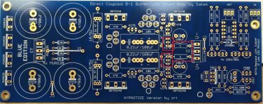
Look at the PCB with the integrated dual polarity PSUAndrew, May I know why?
Thank you.
The o/p impedances of my source now is around 500 ohms, OK to use 10k pot in DCB1?
I will buy another source (CAS player) later, what is the max o/p impedances can I use if I am using 10k pot in DCB1?
The o/p impedances of my source now is around 500 ohms, OK to use 10k pot in DCB1?
I will buy another source (CAS player) later, what is the max o/p impedances can I use if I am using 10k pot in DCB1?
I'd aim for using 50ohms to 200ohms as the source impedance. This is to suit any cables I may want to use. The Rin of the receiver (the DCB1 in this case) is almost irrelevant.
If you keep your source impedance below 1000ohms then that allows you to use short and medium length interconnects. Long interconnects which have high capacitance will not suit.
Some Sources have output impedances around the 2000ohms region. Don't buy/use them.
If you keep your source impedance below 1000ohms then that allows you to use short and medium length interconnects. Long interconnects which have high capacitance will not suit.
Some Sources have output impedances around the 2000ohms region. Don't buy/use them.
No, keep it. 22:1 is even a better ratio than with a 20k pot. That 220k resistor is to guard for always having ground reference to the Jfet's gate even if a pot's wiper or a switcher attenuator's contact momentarily breaks its path to ground. Also for when there's no input side pot if DCB1 is used as a non signal level adjustable buffer. Not to produce output DC during such a circumstance. Only needs be high enough resistance value for leaving the pot's log taper unaltered.
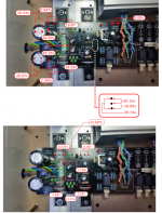
The 0.647V drop on the "dark side" is too low. Measured Vgs of the Mosfet next to it VS its opposite on the other side is bad also.
Measure all Leds and diodes first for Vf with DMM's diode check mode. If its not able DMM for output to light up an Led use a battery and a couple of wires to touch up quickly the Leds pads. 20.16V dark side's out rather says top left Mosfet is gone or shorted externally.
All the mur120 diodes are between 20.55v to 20.74v. The other Mosfet next to the '0.647V drop' measured at 0.00v. But I have just replaced these. in fact these are new Mosfets. I used 1.5v to touch up the LEDs but there are not lighting up as well.
Sorry, those LEDs lights up at 1.8v. 1,5v was too faint i wouldn't see the lights. All LEDs lights up at 1.8v except for one. I'll change that and report back.
Thank you again.
Sorry, those LEDs lights up at 1.8v. 1,5v was too faint i wouldn't see the lights. All LEDs lights up at 1.8v except for one. I'll change that and report back.
Thank you again.
Last edited:
- Home
- Amplifiers
- Pass Labs
- Mezmerize DCB1 Building Thread