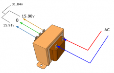

After re-soldered some joints which i think are bad, cleaning up all the soldered area and changing to a new same value transformer (50VA, 15-0-15), these are the measurement. But the transformer still buzzed when plugged in. So, I think it is most likely not the transformer fault. The diodes are in the right position and working good.
Measure the voltage drop across the 300Ω resistors when the voltage across the output relay diode is zero. When is that state of zero? For a moment when you turn the selector? So we try see if at a point two relays draw too much or what else may happens somewhere else at that moment. I am suspicious of the BC517 or BC550 in the output relay control could be broken to a short. Is there Vbe voltage on those during such phases of selection? Is the selector maybe a make before break type?
If inconclusive try this test: Put new BC550 in place of BC517. Put 3.3V 0.5-1W Zener in place of old BC550. Anode to base pad, cathode to emitter pad (BC550 pins are CBE when facing it).
The Zener will fit if standing upright.
The Zener will fit if standing upright.
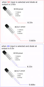
When one of the input is selected, the 300 ohm parallel resistors are at 5.12v across. But when no input is selected, those same parallel resistors are at 2.342v across. I think by right I should be getting around 6v at the output diode, about the same as those I get at the input.
The voltage at the transistors remained the same with or without an input selection. I have even swapped one of the input diode with the output diode. They perform as the same.
Attachments
Last edited:
Vbe ON starts higher for a Darlington normally, at about 1.1-1.2V. Do the modification I proposed so we see what happens.
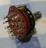
This type of switch selector. 2 pole 6 ways.
Do you have the part number so I can look it up? What happens if you just pull its connector out of the PCB? Any voltages change?
When one of the input is selected, the 300 ohm parallel resistors are at 5.12v across. But when no input is selected, those same parallel resistors are at 2.342v across. I think by right I should be getting around 6v at the output diode, about the same as those I get at the input.
That confirms that only one relay coil is pulling current (the output's) when no input is selected, thus the resistors drop is smaller, and about twice the current goes through when an input is selected (two relay coils powered). The system should always have two relays working (one input and the output) for enough drop across those resistors. At the output diode you should be getting the same like at others minus the BC517 Vcb drop which seems much and eats coil's voltage.
With the zener in placed of the BC550 and a new BC550 in the place of BC517 :
Voltage across the 300 ohm parallel resistor : 7.18v
Across the output diode : 4.54v
Across one of the input : 4.68v
Across the zener : 2.18v
DC offset at 1.7mV
On the right side offset is 0v but on the left side it is 1.7mV.
If no input is selected, the output diode measured at 6.63v across.
Now I can hear the output relay clicking about a second or two after switching it on.
Is it safe to connect it to the amp now?
The selector has no code. It was brought at a local store. But it is similar to the one in the picture.
Attachments

If the selector is like in the datasheet I link, which is break before make, its the proper type for this situation. Not to engage two input relays at the transition (three powered on with the output relay) which can bring down their voltage divider rail a lot. If you see its the make before break type by engaging two input relays for a brief ask for one from the datasheet: http://www.mouser.com/ds/2/13/SR2511F-185523.pdfThe selector has no code. It was brought at a local store. But it is similar to the one in the picture.
That's better. But does the transformer still buzz?
Yes and No.
When both the amp and the pre-amp is switch on, the transformer doesn't buzz and it play music. But when it's only the amp is switch on and the pre-amp off, the buzz returns. But at least it is playing music now. Thank you very much.
How do I solve the buzzing transformer?
Last edited:
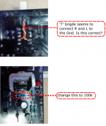
By the way because you got 5V relays, shorter climb time to trigger, you can even replace the 47k resistor (the one next to the 100uF output relay circuit capacitor) with 100k for more delay time if you need.
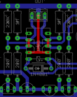
You can also make this mod (add the red lines with wires, watch not to make contact with printed vias blue lines) which is standard in the double layer boards. It was not able to be on your 2008 single layer board. Switches the output to ground instead of opening its signal line when waiting to click or when off. Maybe this solves your remaining buzz?
You can also make this mod (add the red lines with wires, watch not to make contact with printed vias blue lines) which is standard in the double layer boards. It was not able to be on your 2008 single layer board. Switches the output to ground instead of opening its signal line when waiting to click or when off. Maybe this solves your remaining buzz?
Attachments
By the way because you got 5V relays, shorter climb time to trigger, you can even replace the 47k resistor (the one next to the 100uF output relay circuit capacitor) with 100k for more delay time if you need.
You can also make this mod (add the red lines with wires, watch not to make contact with printed vias blue lines) which is standard in the double layer boards. It was not able to be on your 2008 single layer board. Switches the output to ground instead of opening its signal line when waiting to click or when off. Maybe this solves your remaining buzz?
Do you mean replacing the 47k resistor with 100k and also add wires to the relay contact as well?
Switches the output to ground instead of opening its signal line when waiting to click or when off.
I don't think I understand what you mean.
Yes. Create the red lines in the picture with wire. At the underside. Its a T bridge from the second row contact pins to output ground and two short bridges between pins 3-4 per side. Counting from the relay's side facing the diode to back.Do you mean replacing the 47k resistor with 100k and also add wires to the relay contact as well?
I don't think I understand what you mean.
You say a last buzz remains only when preamp is off, power amp is on. So all other buzzes and voltages we solved and I think its not due to the transformer pulled down and the bad voltages anymore that used to give the big problems. But if the output relay will mute to ground and not just cut the output you may solve your last buzz. That one the T wires and the two short bridges shown in red will achieve.
- Home
- Amplifiers
- Pass Labs
- Mezmerize DCB1 Building Thread