Check the DC voltage at the outputs from the regulators (the three pins near the middle of the PCB), should be ~ +10Vdc and -10Vdc and 20Vdc across both.
Check the Vac at these outputs. Should be zero mVac.
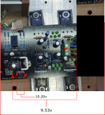
The voltage output (measured from the three pin holes) :
+ 11.73v
- 10.61 v
Across : 22.29v
Vac across : 0v
but across the top and center hole : 0.004v
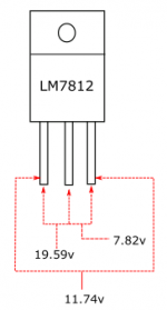
Check the DC voltage at the inputs to the regulators should be ~ +21Vdc and -21Vdc and 42Vdc across both.
Check the Vac at these inputs. Should be near zero mVac if you meter is OK with a high DC bias.
Where do I check the input to the regulator?
On the bottom side the eaiest would be across the smoothing capacitors.
I'll go and have a look at the top side to remind myself what is accessible.
Your 11.7Vdc is a bit high.
I would expect reasonable tolerances to keep you within 0.3V of the nominal ±10Vdc.
I'll go and have a look at the top side to remind myself what is accessible.
Your 11.7Vdc is a bit high.
I would expect reasonable tolerances to keep you within 0.3V of the nominal ±10Vdc.
You should arrange the trafo secondaries connections to the PCB correctly for symmetric high enough DCV resulting across each reservoir capacitor. About 20V DC on each 4700uF capacitor if using 15+15VAC trafo. What is your transformer's spec?
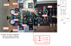
50VA 15-0-15VAC OK, what DC voltage can you measure at points representing the voltage across the reservoir capacitors? Say between the input side of each pair of the 68 Ohm current setting resistors and any ground point?
One capacitor measured across is at 27.52v and the other is at 13.39v. Oh..what is wrong here?
Last edited:
Problem, big problem. Must solve.One capacitor measured across is at 27.52v and the other is at 13.39v. Oh..
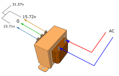
Disconnect the transformer from DCB1. Find its 15-0-15 correct wiring combination of secondaries first with DMM in ACV mode.

So the transformer is good on its own. You also attach the green in the middle screw of the Tx connector on DCB1 and the other two wires to each side, right? If yes, something is pulling one side of your PSU down. Is it the positive side? Is there a short somewhere, an accidental solder bridge? The selector? A wrongly oriented component?
For testing diodes see How to test diodes using a digital multimeter
Also make sure no one is put in reverse to PCB, use a flashlight to inspect up close that their white stripes align with the PCB ones.
For testing diodes see How to test diodes using a digital multimeter
Also make sure no one is put in reverse to PCB, use a flashlight to inspect up close that their white stripes align with the PCB ones.
This is the measurement of the transformer.
These are good.V across the secondaries.
One capacitor measured across is at 27.52v and the other is at 13.39v. Oh..what is wrong here?
if there was an invalid load pulling the supply down that badly, the bulb in the MBT would turn on !So the transformer is good on its own. You also attach the green in the middle screw of the Tx connector on DCB1 and the other two wires to each side, right? If yes, something is pulling one side of your PSU down. Is it the positive side? Is there a short somewhere, an accidental solder bridge? The selector? A wrongly oriented component?
For testing diodes see How to test diodes using a digital multimeter
Also make sure no one is put in reverse to PCB, use a flashlight to inspect up close that their white stripes align with the PCB ones.
The 27Vdc is too high. That points to a miswired rectifier.
Last edited:
After re-soldered some joints which i think are bad, cleaning up all the soldered area and changing to a new same value transformer (50VA, 15-0-15), these are the measurement. But the transformer still buzzed when plugged in. So, I think it is most likely not the transformer fault. The diodes are in the right position and working good.
Attachments
Last edited:
- Home
- Amplifiers
- Pass Labs
- Mezmerize DCB1 Building Thread