the diodes across is 20.66v - 20.73v.
(!) Is the 12V IC regulator blown?
the diodes across is 20.66v - 20.73v. Thats the diodes at the transformer.
For the output diode at each selector turn :
1st diode at first turn = 6.68
2nd diode at 2nd turn = 6.70
3rd diode at 3rd turn = 6.77
OK now your edit explains it good. Is the IC output 12V DC indeed?
All the gnd at the input and output has continuity to the centertap of the transformer. Should they be connected to the chassis? Right now the body of transformer is connected to the chassis but not the input and output gnd.
OK now your edit explains it good. Is the IC output 12V DC indeed?
Which is the IC output?
Why is it that when nothing is selected (the rotary) the diode at the output measured at 2.9v? And when one of the input is selected, the output diode measured 0v. It turned off when each input is selected?
Which is the IC output?
The 7812 IC's output
I asked you to check there at the center tap just because its convenient point for the probe.
There are three holes at middle board for auxiliary regulated +/0/- output. Wire from the middle hole any test to grounding chassis and/or pot
The 7812 IC's output
I asked you to check there at the center tap just because its convenient point for the probe.
There are three holes at middle board for auxiliary regulated +/0/- output. Wire from the middle hole any test to grounding chassis and/or pot
It is the LM7812.
Why is it that when nothing is selected (the rotary) the diode at the output measured at 2.9v? And when one of the input is selected, the output diode measured 0v. It turned off when each input is selected?
The output relay coil powers from same line coming out of the 7812 through the double resistors (which say 2x300 make yours 2x270 which is an easy number) and should be always on. Maybe the rotary shorts that line to ground in some positions?
It is the LM7812.
OK. Does it put out 12V at the input pins of the two same value parallel resistors to its left in respect to ground?
Can I just remove one of the 600 ohm resistors. Just keeping one 600 ohm resistor in the 2 x 300 slots.
No, they are meant to go 150 in more mW because in parallel, but not to go 600. You can piggyback one more 600 on each one not to remove the board and desolder.
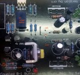
The Signal Flow wire must be close coupled with the Signal Return wire. Use coaxial, or twisted pair or even screened twisted pair.It was done this way in the image. But since all the gnd is connect at the board, should i just use one gnd wire to connect all the rest?
EVERY input socket MUST have a pair of Signal wires all the way to the Receiver.
A 3pin XLR balanced socket complies with this, pin1 goes direct to Chassis, pins 2 & 3 go via a twisted pair to the receiver.
Every inter-module connection MUST use a close coupled PAIR to carry the Signal Flow and Signal Return.
This applies to line level audio signal, cartridge level audio signals, speaker level audio signals, high voltage power supply signals, regulated low voltage power supply signals.
There are no exceptions !
Last edited:
Why are you connecting the Signal Returns to the Chassis?All the gnd at the input and output has continuity to the centertap of the transformer. Should they be connected to the chassis? Right now the body of transformer is connected to the chassis but not the input and output gnd.
I have removed all connection form the board. The 2 x 600 resistors are indeed 300 ohm resistors. I measured them and they are at 298 ohm Sorry for the wrong info. The problem is with the transformer. The amp buzz even without anything attached to the transformer. Which means, just plugging in the transformer the amp goes buzzing.
Attachments


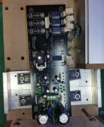
Check that the green wire at power entry is really the centre tap at the transformer.
This would be better twisted, rather than plaited.
I don't like your exposed mains terminals close to your metal work !
Check the DC voltage at the inputs to the regulators should be ~ +21Vdc and -21Vdc and 42Vdc across both.
Check the Vac at these inputs. Should be near zero mVac if you meter is OK with a high DC bias.
Check the DC voltage at the outputs from the regulators (the three pins near the middle of the PCB), should be ~ +10Vdc and -10Vdc and 20Vdc across both.
Check the Vac at these outputs. Should be zero mVac.
Last edited:
Check that the green wire at power entry is really the centre tap at the transformer.
This would be better twisted, rather than plaited.
I don't like your exposed mains terminals close to your metal work !
The mains terminals are about an inch away from the metal case. You mean twist all three wires rather than plait them?
Yes, twisted pair/triplet gives closer contact and smaller loop area than plaited. That equals less emi.
Keep in mind that only one power Flow wire passes significant current at a time. The other passing virtually none.
So you have one power and the Return wire acting as the close coupled pair. Then half a cycle later it's the other power wire and the Return that acts as the flow and return pair.
You have to keep each of those pairs close coupled all the way from the source to the receiver. The twisted triplet achieves this.
Last edited:
- Home
- Amplifiers
- Pass Labs
- Mezmerize DCB1 Building Thread