Thank you, George.With loudspeakers, I too prefer the Aurak (space and more clear treble).
Yes, I too prefer the detail, sense of openness and forward shape to the performance of Aurak in those recordings. But also, in general, I came to settle on a variant of Aurak V3 as my main listening preamp since a few years ago.
Good to add the M97 to the list of can carts that work well with transimpedance loading. And yes it does stand up well to the DL-103/Hagerman Bugle in those recordings, preferable even, IMO.
LD
Last edited:
Thank you, George.
Yes, I too prefer the detail, sense of openness and forward shape to the performance of Aurak in those recordings. But also, in general, I came to settle on a variant of Aurak V3 as my main listening preamp since a few years ago.
Good to add the M97 to the list of can carts that work well with transimpedance loading. And yes it does stand up well to the DL-103/Hagerman Bugle in those recordings, preferable even, IMO.
LD
Just imagine how well a fully differential Aurak would be sounding
Hans
Rather off topic but here it is.What I'm referring to is BANDWIDTH LIMITATION which is much less well known. If you do DBLTs with and without a sharp cut filter above eg 17kHz, you find that of those who can reliably tell the difference, the preference is ALWAYS for the bandlimited channel.
I obviously misunderstood the outcome, because the result was in favour of the filter switched on.
That was what upset all the participants.
Hans
AES Netherlands section members perform listening tests – Part II introduction
In April 2013, several members of the NL section of the AES gathered to do some listening experiments related to the audibility of phase shifts and brick-wall filtering.
The opportunity arose because one of the members (Richard van Everdingen) had acquired a vintage stereo coder. This particular filter was flat within +/- 0.1dB out to 15kHz and
dropped to -60dB at 19kHz. The signal is phase shifted increasingly with frequency, reaching 360 degrees at 15kHz.
The purpose of the meeting was to perform informal but controlled listening tests to find out whether this filtering and phase shift are audible.
The results have been reported at the NL AES LinkedIn forum and the AES sections area (NL section).
The participants were able to consistently identify the two versions, but preferred the filtered version over the non-filtered version, stating that to them the filtered version had better attack and sounded more ‘crisp’.
Differences were reported to be subtle and to require considerable effort to correctly identify.
Rather off topic but here it is.
I obviously misunderstood the outcome, because the result was in favour of the filter switched on.
There are hidden confounders in this test related to amplifier and speaker issues of HF IM. All these DBT tests are way harder to do right than folks think.
OK. Thanks for this Hans. No surprises.I obviously misunderstood the outcome, because the result was in favour of the filter switched on.
The result is the same as EVERY PROPERLY CONDUCTED DBLT on BANDWIDTH LIMITATION conducted in this or the previous Millenium including my own tests.
If you want to sell a device that with REALLY AUDIBLY IMPROVE ANY AUDIO SYSTEM, you might want to market a brickwall filter at 20kHz. Only for true golden pinnae of course. Da audiophools who hear 'chalk & cheese' differences between mains cables needn't apply cos they are not discriminating enough.
Yes. I pontificate a little in the thread on Wayne's forum that Hans contributed to.There are hidden confounders in this test related to amplifier and speaker issues of HF IM. All these DBT tests are way harder to do right than folks think.
It's a HUGE subject and I could write a book on it. Don't even think the ABX crowd, Lipshitz & Vanderkooy, Olive, Toole & the Harman gang et al have the full story.
BTW, I can pretend to explain the results of my previous Millenium results but not the tests this century on digital material which is already bandlimited.
Last edited:
This isn't strictly true.The result is the same as EVERY PROPERLY CONDUCTED DBLT on BANDWIDTH LIMITATION conducted in this or the previous Millenium including my own tests.
There was ONE (and only ONE) properly conducted test in da previous Millenium that showed the converse .. but it doesn't change the practical advantages of my Cooktown Recording and Ambisonic Productions SuPa Dupa Black Box (a 19khz multiplex filter screwed up to become a 20kHz brickwall but don't tell anyone 😀 )
http://www.americanradiohistory.com/Archive-Poptronics/70s/1970/Poptronics-1970-09.pdf
Apologies for the link. I'm sure I've seen a better description of the Experiment that save HiFi - Olson on the www.
Last edited:
Apologies for the link.
Those were the days.
"MALE- FEMALE HYPNOTISM" EXPOSED, EXPLAINED! "SECRET METHOD" -THEY NEVER KNOW! $2, RUSHED. GUARANTEED! ISA- BELLA HALL, SILVER SPRINGS, FLORIDA 32688.
Here's 2p worth as to cart-arm resonant system and damping.Maybe LD could give some comment on damping in the horizontal plane only.
With my arm Fr vert is much better damped as Fr hor, causing the IM products produced by a horizontally cut 1Khz test tone to be clearly visible (#724).
Could it be that in general most of the needle movement is in the horizontal plane, but that noise (from a blank track) is only in vertical direction ?
That would explain why I hardly see any resonance in the noise spectrum, but when playing infrasonic tones horizontal resonance is clearly visible.
Hans
The system is continuous and not-symmetrical in 2D. So, in reality, restoring headshell motion in response to a displacement typically typically describes a lissajous curve in 2D as it settles. The vector for much initial headshell displacement is typically more vertical than lateral, partly because many causes send the stylus upward (it isn't free laterally).
However, stylus-groove friction, or variation in it, is typically the largest cause of displacement other than eccentricity/warp, and acts by instantaneous variation of skate force to displace the headshell.
IIRC you have a linear tracking arm, Hans, so only vertical vector of stylus-groove friction is at issue, applied via the 20 deg or so cantilever VTA, and perhaps this might be an explanation ?
More generally, the enemy is displacement of the headshell from a perfect locus following the groove. And the principle audible effect is pitch modulation (FM) of programme material due to stylus scrape. So the issue of choosing a 'resonant frequency' such as nominally 10Hz is not as important as the Q which is set by damping, and the settle time which follows on from it.
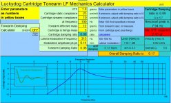
A few years back I wrote a low frequency mechanics predictor called 'loafer', which pulled together the many and various parameters from cartridge and arm, and attempted to predict required VTF for trackability and settle time. Attached is a screenshot for a typical cart/arm combination.
Most cart/arm combinations are sub-optimally damped IMO and would benefit from extra arm or brush damping. Loafer helps calculate how much damping to apply in terms of torque at the headshell.
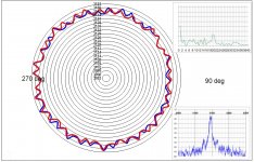
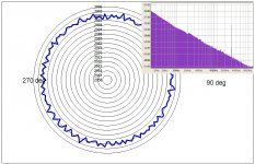
Also attached is a plot which looks at pitch stability in an interesting and very human way. Once around the plot is one revolution of the platter. Radius is 'instantaneous' pitch of a 3150Hz test tone, measured by accurate and low noise FFT with a bandwidth of about 50Hz. The plot shown is for a cart/arm with a resonance at c 20Hz, and fairly normal Q. Inset is a conventional B&K style spectrum plot, and also the FFT spectrum of the pitch modulation. One radial line is meant to represent the threshold of audibility of pitch modulation.
I think collectively this illustrates what is important about the cart-arm resonant system: pitch stability which is linked to Q.
LD
Attachments
Its a pitty that exactly the part describing how Olson performed his tests is missing.This isn't strictly true.
There was ONE (and only ONE) properly conducted test in da previous Millenium that showed the converse .. but it doesn't change the practical advantages of my Cooktown Recording and Ambisonic Productions SuPa Dupa Black Box (a 19khz multiplex filter screwed up to become a 20kHz brickwall but don't tell anyone 😀 )
http://www.americanradiohistory.com/Archive-Poptronics/70s/1970/Poptronics-1970-09.pdf
Apologies for the link. I'm sure I've seen a better description of the Experiment that save HiFi - Olson on the www.
But anyhow, placing a filter in line means both removing information and some added distortion and adding phase distortion.
That the result might be preferred is like the photo-shopping of professional models like Victoria Secret's Angels, because that is supposed to make them better looking. What a waste.
Hans
If we are going to go that far back, these are also worth reading.
http://www.americanradiohistory.com/Archive-Audio/40s/Audio-1947-Aug.pdf
http://onlinelibrary.wiley.com/doi/10.1002/j.1538-7305.1931.tb02334.x/epdf
Important note regarding Scott’s mention of con-founders: Olson’t test (where winner was full range music) was with a live band playing (not electric playback) and the LP filter was acoustic.
George
Important note regarding Scott’s mention of con-founders: Olson’t test (where winner was full range music) was with a live band playing (not electric playback) and the LP filter was acoustic.
George
That might reinforce the point in fact that there is some issue when speakers are involved.
Yes. That's why I mentioned it.
It removes the possible influence of distortion from the microphone, electronics and loudspeakers.
George
It removes the possible influence of distortion from the microphone, electronics and loudspeakers.
George
I'm sure I've seen an article which more fully described the test. There's also the formal paper.Its a pitty that exactly the part describing how Olson performed his tests is missing.
I'm sure da audiophools prefer stuff that makes music sound worse as long as it has a "hand carved from solid Unobtainium by virgins" label 🙂But anyhow, placing a filter in line means both removing information and some added distortion and adding phase distortion.
That the result might be preferred is like the photo-shopping of professional models like Victoria Secret's Angels, because that is supposed to make them better looking. What a waste.
The true golden pinnae .. those who get consistent results in DBLTs .. ie not deaf .. usually prefer stuff that makes music sound better 😀
I'm really a speaker & mike designer who has dabbled extensively in electronics, DSP bla bla etc. I was a real DBLT guru in my previous life and have had some success using DBLTs to design stuff which sounds better.
Of course taking this trouble for da audiophools is a waste of time as they don't appreciate better sound. For these important customers, the best strategy is to tell them loudly and repeatedly that your stuff is hand carved from solid Unobtainium by ... shut up Lee! Just SHUT UP!!
Last edited:
A few further points of explanation about the plot.Also attached is a plot which looks at pitch stability in an interesting and very human way. Once around the plot is one revolution of the platter. Radius is 'instantaneous' pitch of a 3150Hz test tone, measured by accurate and low noise FFT with a bandwidth of about 50Hz. The plot shown is for a cart/arm with a resonance at c 20Hz, and fairly normal Q. Inset is a conventional B&K style spectrum plot, and also the FFT spectrum of the pitch modulation. One radial line is meant to represent the threshold of audibility of pitch modulation.
Red and Blue plots are successive rotations of the platter. This is handy to separate pitch variation which arises once per rotation, such as eccentricity/warp, from pitch variation that arises from non-synchronous causes such as pseudo-random headshell motion.
What one finds, from looking at a reasonable number of these plots, is that spindle motor/drive speed variation is typically very small compared to eccentricity/warp and headshell induced FM pitch variation. For all reasonable turntables, and unless there is a fault.
I collected 3rd party samples of 3150Hz or 3000Hz test tones, from most of the best reputed and highly regarded TTs. Conclusion was clear, and perhaps surprising: it is far more productive to invest in headshell stability rather than platter speed stability, unless there is a fault. So addressing tonearm damping is far more useful for improving audible pitch stability than addressing motor speed variation. Cartridge choice, surprisingly, can be a big factor IME.
If anyone is interested in analysis of their rig this way, please post a short recording of a 3150Hz or 3000Hz test tone. About 10s, and any lossless format and any level that doesn't clip is fine. I don't mind doing a few every now and then.
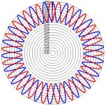
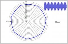
Meantime, here's some pretty calibration plots, one of which I used as an avatar a few years back.
LD
Attachments
Last edited:
I'm sure I've seen an article which more fully described the test.
See the AUDIO article (1st link post #752)
There's also the formal paper.
Olson, H. F. (May 9, 1947). Frequency range preference for speech and music. J. Acoust. Soc. Am. 19, 549–555.
George
If anyone is interested in analysis of their rig this way, please post a short recording of a 3150Hz or 3000Hz test tone. About 10s, and any lossless format and any level that doesn't clip is fine. I don't mind doing a few every now and then.LD
Nice offer.
What should be the minimum sample rate ?
Hans
Min 22kHz/16 lossless. Any sample rate/depth prefered for convenience, but not essential.Nice offer.
What should be the minimum sample rate ?
Hans
LD
Doh - any better sample rate/depth preferred for convenience, but not essential. In practice, 44.1/16 is fine.Min 22kHz/16 lossless. Any sample rate/depth prefered for convenience, but not essential.
LD
- Home
- Source & Line
- Analogue Source
- mechanical resonance in MMs