Previously it has been shown that the LF resonance can be measured using a silent groove. Can the HF frequency response also be measured the same way? Would be great if it could as would remove all the questions over test record sweep accuracy...
Back in the 70s I saw a test where the cartridge was dropped from a couple of inches onto the LP.
The electrical output was FFT processed as a step function into the frequency response.
Think they used an HP dynamic signal analyzer. It seemed to work reasonably well.
Of course that would be the vertical response.
The electrical output was FFT processed as a step function into the frequency response.
Think they used an HP dynamic signal analyzer. It seemed to work reasonably well.
Of course that would be the vertical response.
Last edited:
Yes, I’ve seen this done but I suspect the basis is fundamentally flawed. If the ‘silent groove’ is really silent, then there should be no stimulus and no output at all. If the ‘silent groove’ is stimulating LF resonance, then I suspect that the groove is really not silent. The stimulus is likely coming from one or more such things as: micro variations in formulation of the lacquer master or the vinyl pressing (causing amplitude variations), or some groove drag variation akin to scrape flutter on a tape deck. Note that if there are groove drag variation effects, then the dynamically varying drag force pulling on the cantilever would resolve into vertical and horizontal forces that excite both modes of resonance.Previously it has been shown that the LF resonance can be measured using a silent groove. Can the HF frequency response also be measured the same way? Would be great if it could as would remove all the questions over test record sweep accuracy...
If ‘silent groove’ stimulus is causing LF resonance, and maybe even HF resonance, then the stimulus in silent groove pressings might vary from manufacturer to manufacturer or even from different batches of vinyl from the same manufacturer, so you’re back to square one in terms of test record accuracy and non-uniformity.
Reminder: Along with the amplitude effects of LF resonance, the stylus scrubbing along the groove introduces FM distortion. In the vertical mode, the FM for a given resonance amplitude is primarily dependent on the VTA of the cartridge cantilever. In the horizontal mode, the FM for a given resonance amplitude is primarily dependent on the offset angle of the cartridge/arm combination.on the silent groove issue https://www.diyaudio.com/community/...-compliance-compatability.367565/post-6533937 . Does seem to show that linear trackers really are the way forwards if you can live with their other foibles.
well silent grooves are never really silent. They are full of low level noise (hopefully white). Tests still ongoing but certainly the shape of the Frequency response can be seen on a lead in groove.


Your noise floor seems really low
Vinyl noise when the needle tracks the start is 15db higher then preamp noise.
My preamp is about 83 dB s/n.
The vinyl noise is 2khz and below, for the most part is masked. I am using a vm15 type 2 cart.
Vinyl noise when the needle tracks the start is 15db higher then preamp noise.
My preamp is about 83 dB s/n.
The vinyl noise is 2khz and below, for the most part is masked. I am using a vm15 type 2 cart.
The Ultimate LP is much quieter above 100Hz.The FFT of vinyl silence
George
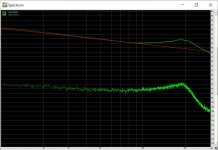
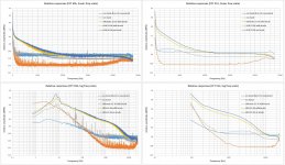
Teaser shot. Teaser as I'm still trying to find time to analyse it fully. Top trace is pink noise track, bottom trace is the lead in groove. This is an experimental stylus and I'm not sure the experiment was successful as the cantilever Fres does appear in the audio band but is a very useful analytical tool as the original Be cantilever (as shown on here earlier) is flat to well above 30kHz.
Attachments
George,The FFT of vinyl silence
George
Two flat objects rubbing each other produce white noise above a certain speed with a certain level because of the coefficient of friction u=F/N where F is is the frictional force and N is the normal force.
Above a certain speed of movement, the so called knee point, the frictional force F remains constant.
A needle rubbing over Vinyl is no exception to that.
For an LP this knee point is somewhere around 500Hz. Above 1Khz the white spectrum will be multiplied by the Carts FR.
So when looking at the noise produced by an unmodulated groove, look above 1Khz and you will roughly see the Carts FR, but only when playing over a straight non Riaa amp.
When using a Riaa preamp, the Riaa curve and the Cart FR curve will both modify the spectrum.
Also be aware that because of the low level of the signal, the A/D's quantization noise has to be well below the recorded noise.
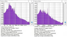
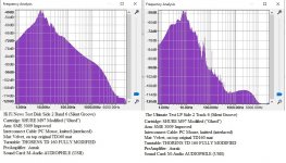
The first image was taken from inner diameter lead out groove of just some LP and the second image shows the spectrum of the carefully made HiFi LP that you also used, side 2, track 6.
Quite obvious there is hardly a difference, proving the above point.
What you can see is that my Cart has a resonance at ca 65 Khz.
Hans
P.,S. Your second set of images with the Shure has twice the same subscript but the spectra are different, how is that ? Maybe Left and Right channel ?
Also keep in mind that Audacity produces very inaccurate spectra and should not be used for this sort of things.
Attachments

Hi Hans
Thank you for the as usually informative post.
Now a few more thinks for clarification.
I posted here only to show that there is life in silent grooves from all sources (vinyl composition, cutting equipment, playback system), the most prominent at lower frequencies.
The second attachment in my last post, is from silent groove on two different test disks, that’s why you see such different FFTs (it happens that both are located on Side 2 and are both Track 6).
The way Audacity presents it’s FFTs is not that good, I agree. Whether it’s FFT data is wrong, I can’t say. If you have evidence please inform us.
There is a way for better presentation of FFT from Audacity. There is the function of exporting the FFT data in .txt format (freq/level pairs), then to a spreadsheet. I did it and plots are attached below. (I noticed you showed your results in linear freq scale, so I added that too). Unfortunately there were sampled to 24kHz only (old recordings)
The RIAA preamp is your excellent Aurak trimmed for the M97xE
Cartridge: SHURE M97 Modified (“Glued”)
Arm: SME 3009 Improved
Interconnect Cable: PC Mouse, knitted (interlaced)
Mat: Velvet, on top original TD160 mat
Turntable: THORENS TD 160 FULLY MODIFIED
PreAmplifier: Aurak on batteries
Sound Card: M-Audio AUDIOPHILE (USB)
Attachments
Hi George,Hi Hans
Thank you for the as usually informative post.
Now a few more thinks for clarification.
I posted here only to show that there is life in silent grooves from all sources (vinyl composition, cutting equipment, playback system), the most prominent at lower frequencies.
The second attachment in my last post, is from silent groove on two different test disks, that’s why you see such different FFTs (it happens that both are located on Side 2 and are both Track 6).
The way Audacity presents it’s FFTs is not that good, I agree. Whether it’s FFT data is wrong, I can’t say. If you have evidence please inform us.
There is a way for better presentation of FFT from Audacity. There is the function of exporting the FFT data in .txt format (freq/level pairs), then to a spreadsheet. I did it and plots are attached below. (I noticed you showed your results in linear freq scale, so I added that too). Unfortunately there were sampled to 24kHz only (old recordings)
The RIAA preamp is your excellent Aurak trimmed for the M97xE
Cartridge: SHURE M97 Modified (“Glued”)
Arm: SME 3009 Improved
Interconnect Cable: PC Mouse, knitted (interlaced)
Mat: Velvet, on top original TD160 mat
Turntable: THORENS TD 160 FULLY MODIFIED
PreAmplifier: Aurak on batteries
Sound Card: M-Audio AUDIOPHILE (USB)
What I prefer in order to get the Spectra I'm looking for, is by using the soundcard to record and save a .wav with Audacity preferably in 196/24.
Then use Rmaa to investigate this .wav file by selectin the green box called "spectrum Analyzer".
Rmaa can turn a .wav file of up to 2 minutes in one go into an FFT while overlapping, filtering and having the option to use a different filter bin width.
The graph produced by Rmaa can be zoomed in, have a log or linear scale and so on.
The spectra are among the most correct that you can wish.
Hans
Not sure, if it was already mentioned in this thread, but the old B&K approach, using an accelerometer to measure the frequency response of a cartridge could help to examine the influence of the vinyl properties.
https://www.bksv.com/media/doc/TechnicalReview1976-2.pdf
https://www.bksv.com/media/doc/TechnicalReview1976-2.pdf
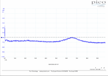
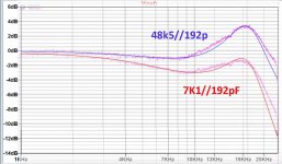
No updates for a few days as some investigations have been ongoing that should be filed under 'because we can'. No one has really asked the question before as to what would happen if you took a high compliance cartridge that was nicely optimised for a lightweight cantilever and put a different cantilever on which doubles the effective tip mass. But we happened to have one such cartridge so decided to test it It has proven a very helpful analytical tool and may have driven a breakthrough. I'll leave Hans to post about that, but we have a plausible model for why some cartridges show a dip in response around 5kHz.
Delay will be a little longer as we want to gather more data to confirm the theory, but here is another teaser of our high tip mass high compliance franken cartridge with predicted frequency response overlaid with measured frequency response. The cantilever model was set for normal loading and then a very much lower restive loading was tried to confirm the cantilever model was on the right track. Sample of one looks good now to compare with the original stylus that was fitted to it.
Attachments
- Home
- Source & Line
- Analogue Source
- mechanical resonance in MMs