Minimum phase is often misunderstood. It just means you can calculate the phase from the magnitude response with a Hilbert-Bode transform and it will match the measured phase after the appropriate time-of-flight is subtracted. It doesn't mean zero phase unless the magnitude response is perfectly flat.
ARTA is nice for measuring phase because you can plot excess phase (measured - minimum.) Then you can change the time of flight while watching the excess phase, trying to get it flat and near zero at your crossover point. Or, as an alternative, you can set minimum phase as an overlay and change time-of-flight so the two curves match up.
ARTA is nice for measuring phase because you can plot excess phase (measured - minimum.) Then you can change the time of flight while watching the excess phase, trying to get it flat and near zero at your crossover point. Or, as an alternative, you can set minimum phase as an overlay and change time-of-flight so the two curves match up.
Oliver, I think you are correct: the huge problem with small listening rooms is that there is too much correlated sound reflecting about in them at SPLs that are too high compared to those of the decorrelated sound.. . as compared to the situation in performance spaces - even relatively small ones.
This tends to wreck the reality illusion we are striving for.
It actually would be a good idea to have a thread about this topic.
The multiple subs thread touches on this topic.
This tends to wreck the reality illusion we are striving for.
It actually would be a good idea to have a thread about this topic.
The multiple subs thread touches on this topic.
For those who are interested, fig. 16 on page 8 shows a new
kind of directivity which can be obtained with distributed mode
loudspeakers, but may not be restricted to that techology.
http://www.fmhearing.com/pdfs/NXT_Tech_Review.pdf
There is not only a polar dispersion in sound pressure but
also in phase correlation. This is a way to overcome
the mutually exclusive habits of wide vs. narrow radiating
piston loudspeakers in adding a further angle dependent
dimension.
Loudspeakers able to exhibit coherent sound towards the
main radiation axis and sound decorrelating at larger
angles at the same time, cirmumvent the dichotomy of
properties present in narrow vs. wide radiating piston
acting loudspeakers, which were discussed above in this
thread.
It is an option which should be named at least,
as it seems widely unknown or unaccepted from parts of the
professional audio community up to now.
The new spatial radiation properties have a tremendous effect
on the disturbances introduced by early room reflections e.g. in
that imaging and measured transmission characteristics get far
more robust against the interference effects present in
untreated rooms.
Angle dependent phase correlation is usually not measured
when using piston acting speakers. It did not seem interesting,
because piston acting loudspeakers will normally have highly
correlated phase even at larger angles.
But that does not imply the new indicator being insignificant in
its frequency and angle dependency for it is not very wise to
assume something being unimportant just because it is commonly
forgotten or unknown due to recent "state of the art".
The recent state of the art is not building good loudspeakers, but
acoustical problems with respect to the properties of the untreated
acoustical small room.
Yes, but that is to demonstrate the mathematical basis. As he has pointed out in other posts, if the result was not minimum-phase, then all of our software for designing and predicting response, that is shown to be highly reliable, would be useless. In addition, the response of a multi-driver system with crossovers would not sum as predicted, either, the crossovers would not themselves work.
The "ripple of mutiple arrival times" is in essence what always occurs either with diffraction of box systems or of dipoles. The only difference with dipoles is the 6db slope. But look at baffle step of boxed systems. It is a 6db change in a step. Below the step the output is again constant. The only issue is the peaks and dips around the step. We make raw measurements that inherently include all of this. These measurements are routinely shown to be minimum-phase by all software used to model it. In addition, all diffraction/dipole effects are distributed, yet again the results are routinely shown to be minimum-phase empirically.
I'm not sure what examples would fit your description. Any non-point source driver (all of them in reality) has multiple sources, since all real-world drivers are not infinitely stiff, hence the output from a driver is an integration of all of these time-delayed and non-coincident sources. The issue comes in when we add filters to the drivers.
Dave
Sorry, but I'm not sure what your definition of minimum phase is. Minimum phase means a system who's phase response is equal to the Hilbert transform of the frequency response (fixed group delay or air path delay aside). In other words it includes the minimum phase shift to achieve the amplitude response, it has no excess phase. It contains no all pass components. In pole zero terms the zeros are in the left half plane. No left plane poles are canceled by right plane zeros (another definition of an all pass).
Wikipedia is pretty good on this (towards the bottom)
Minimum phase - Wikipedia, the free encyclopedia
Multiple path systems are generally non-minimum phase since one or more all-passes would be required to give the delay of at least one of the sections.
Loudspeaker drivers are nearly always minimum phase (the individual drivers alone). Whizzer cone woofers are an exception. Two way systems are nearly always not minimum phase, primarily because we design them to have fairly flat response while the delay time of the drivers is different due to different depths of the acoustic centers. Again, the different driver delays are equivalent to an all pass component.
Finally, the crossovers do not make the system non-minimum phase , it is the different driver acoustic centers. (All simple crossovers are minimum phase. Cascading minimum phase sections yields a minimum phase combination.) Also, I don't know of any software that requires systems to be minimum phase for proper modeling as long as the interunit time delays are accounted for.
David
Precisely.Sorry, but I'm not sure what your definition of minimum phase is. Minimum phase means a system who's phase response is equal to the Hilbert transform of the frequency response (fixed group delay or air path delay aside). In other words it includes the minimum phase shift to achieve the amplitude response, it has no excess phase.
For most systems, yes. There are only a few exceptions. John's post was originally on the topic of dipoles and the back side wave when it is diffracted. That, though a multi-path "system"as it were, is minimum-phase as a system since as he explains, the front wave is M-P, the back wave is M-P and the combined response is M-P. Measurements demonstrate this as well as the math he presented. I certainly would not dispute his math, especially given that empirical evidence fully supports the theory.Multiple path systems are generally non-minimum phase since one or more all-passes would be required to give the delay of at least one of the sections.
Yes to the first part, I can't comment on whizzers as I've never measured any.Loudspeaker drivers are nearly always minimum phase (the individual drivers alone). Whizzer cone woofers are an exception.
Two way systems are nearly always not minimum phase, primarily because we design them to have fairly flat response while the delay time of the drivers is different due to different depths of the acoustic centers.[/QUOTES]
It's more likely due to the need to use higher order filters, but the drivers do have to be aligned if active delay is not used for a system to be minimum-phase if of the required crossover that may produce it.
No disagreement here. I think we're on the same page up to here. My comments were related to raw drivers primarily.Again, the different driver delays are equivalent to an all pass component.
Here I have to disagree. A minimum-phase system has several requirements. Acoustic centers aligned (or active delays) is just one. With that satisfied, the crossover used is critical if minimum-phase is to be attained for the system. Essentially these are the issues related to transient-perfect systems.Finally, the crossovers do not make the system non-minimum phase , it is the different driver acoustic centers. (All simple crossovers are minimum phase. Cascading minimum phase sections yields a minimum phase combination.)
Software is written based on the assumption (and reality) that raw drivers are minimum-phase as measured. Without this we would be, as I think John said in another post, working with trial and error. Model and optimization packages show extremely close correlation, so empirically it's an easily provable condition.Also, I don't know of any software that requires systems to be minimum phase for proper modeling as long as the interunit time delays are accounted for.
David
Dave
The rest of your harangue is not even worthy of response.
Dave
Hi Dave - personally I don't think that any of it has been.
We may be mincing words here but...
You had said that the final system would need to be MP for the software to work. I had said that the sections are assumed MP (even this isn't required for softwre that imports actual phase) but the combinations aren't and the software had no problems with that.
David Smith
I can't refute the math but I'm not comfortable with his conclusion. I know if you took an electrical circuit with two paths, one with a delay equivalent to the dipole's front path and a second with delay equivalent to the rear sound's path, it would be considered a typical example of a non-minimum phase system. It certainly isn't true that two minimum phase systems added must be minimum phase. (Just that they might be.)For most systems, yes. There are only a few exceptions. John's post was originally on the topic of dipoles and the back side wave when it is diffracted. That, though a multi-path "system"as it were, is minimum-phase as a system since as he explains, the front wave is M-P, the back wave is M-P and the combined response is M-P. Measurements demonstrate this as well as the math he presented. I certainly would not dispute his math, especially given that empirical evidence fully supports the theory.
Software is written based on the assumption (and reality) that raw drivers are minimum-phase as measured. Without this we would be, as I think John said in another post, working with trial and error. Model and optimization packages show extremely close correlation, so empirically it's an easily provable condition.
Dave
You had said that the final system would need to be MP for the software to work. I had said that the sections are assumed MP (even this isn't required for softwre that imports actual phase) but the combinations aren't and the software had no problems with that.
David Smith
For most systems, yes. There are only a few exceptions. John's post was originally on the topic of dipoles and the back side wave when it is diffracted. That, though a multi-path "system"as it were, is minimum-phase as a system since as he explains, the front wave is M-P, the back wave is M-P and the combined response is M-P. Measurements demonstrate this as well as the math he presented. I certainly would not dispute his math, especially given that empirical evidence fully supports the theory.
Dave
Hi Dave and Dave
An interesting discussion on MP. I have discussed this in the past with John to some extent. The fact is that MP just never comes up in acoustics, is a SISO system concept and I never view acoustics that way. In my mind Dave S makes some good points and DLR basically reiterates JohnK's point of view. Thinking about this, a question comes to mind. If two sources differ in path length and this is not corrected in the crossover, then its MP, as I understand the discussion. Then why is a dipole MP since it is clearly two sources with different path length? Seems contradictory to me. And when would a dipole be nonMP?
As I said MP is not a concept that I have ever used in a design and its never taught in acoustics (search the index of any standard Acoustics text and you won't find this term) so I'm not a real expert.
Hi Earl,
I was hoping you could weed through John's math. (I was asleep during that class.)
That's the point in dispute.
Seem's like John is discussing a system with the sole characteristic of an added first order rolloff, yet his models define two impulses. I'd have thought the two impulses would force it to be Non-MP.
I do recall that Bell Labs did a paper once that showed that the response a speakerphone in a live room could be minimum phase based on the level of the room reflections, an unexpected result.
David
I was hoping you could weed through John's math. (I was asleep during that class.)
If two sources differ in path length and this is not corrected in the crossover, then its MP, as I understand the discussion.
That's the point in dispute.
Seem's like John is discussing a system with the sole characteristic of an added first order rolloff, yet his models define two impulses. I'd have thought the two impulses would force it to be Non-MP.
I do recall that Bell Labs did a paper once that showed that the response a speakerphone in a live room could be minimum phase based on the level of the room reflections, an unexpected result.
David
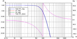
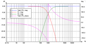
I have to agree with dlr. An individual driver plus its crossover filter will be minimum phase. But when you add a woofer and a tweeter, the sum is no longer minimum phase, it's an allpass (no magnitude change but the phase shifts). Here's a sim with 'perfect' drivers, flat from 1Hz-50kHz, and an LR4-1000 crossover. Both the drivers have identical acoustic centers.Finally, the crossovers do not make the system non-minimum phase , it is the different driver acoustic centers. (All simple crossovers are minimum phase. Cascading minimum phase sections yields a minimum phase combination.)
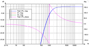
The lowpass filter is minimum phase. It rotates 360 degrees from DC to light and the rotation is 180 at 1kHz, just as you'd expect from a 4th order filter.
Same thing for the highpass filter.
But the sum is not minimum phase. The phase still rotates 360 degrees. The magnitude sum is flat. If the sum were minimum phase, the summed phase would be flat and zero.
Attachments
Last edited:
I have to agree with dlr. An individual driver plus its crossover filter will be minimum phase. But when you add a woofer and a tweeter, the sum is no longer minimum phase, it's an allpass (no magnitude change but the phase shifts). Here's a sim with 'perfect' drivers, flat from 1Hz-50kHz, and an LR4-1000 crossover. Both the drivers have identical acoustic centers.
Thanks for the nice graphs but I think ou are illustrating my point.
To be clarify what I had said, cascaded minimum phase sections, whether acoustical or electrical would give a minimum phase result. Cascaded would mean series connected elements such as your "individual driver plus its crossover filter". It is when we have parallel sections that we get into trouble.
So your woofer and crossover would be MP, your tweeter and crossover would be likewise MP, but their parallel combination (not cascade) would not be MP except for a few special cases (such as time aligned units with subtractive crossovers, etc).
Now, lets go back to the original issue. If instead of a dipole we had two sealed enclosure woofers with one behind the other by a distance of half our dipole baffle width. We'll then connect the farther one out of phase and roll off its highs to some degree. Would we expect the combination (both playing) to give a minimum phase result?
David S
Hi Earl,
I was hoping you could weed through John's math. (I was asleep during that class.)
That's the point in dispute.
I do recall that Bell Labs did a paper once that showed that the response a speakerphone in a live room could be minimum phase based on the level of the room reflections, an unexpected result.
David
Looks like what you quoted me on was said wrong
- my mistake, that should read "non-MP"If two sources differ in path length and this is not corrected in the crossover, then its MP, as I understand the discussion.
I didn't study John's math in detail - the whole topic isn't that interesting to me to take that time, as I said, it's not an acoustical concept.
But this I know (Bell Labs, Jont Allen): No matter what the characteristic of the source, its "room response" is not MP. That begs the question. If the source is MP, then at what point does it become non-MP? Does this happen at the first reflection? Second? gradually? All of a sudden? It seems pretty grey to me.
For the curved cone woofer as the frequency through the narrow region where phase changes from positive to negative the energy emission is quite flat so the simple frequency response is flat. Flat frequency response on axis is and was the goal in development of the curved cone woofer. At that point of zero coherence there is no real phase at all or useful information radiated from the woofer. I have posted graphs on several threads showing results of non-minimum phase behavior as all drivers exhibit. As example:
http://www.diyaudio.com/forums/multi-way/161627-horn-honk-wanted-68.html#post2160891
This result is from a computer and software driven system which in this case has be verified to deliver correct information within certain parameters. These parameters were carefully reviewed to assure resultant test were correct.
As for minimum phase, if that were true this thread and all its' discussions would not exist!
http://www.diyaudio.com/forums/multi-way/5699-cant-reproduce-square-wave.html
There is no such thing as a minimum phase woofer or at least in 44 years I have not seen one. If there is such a thing then by all means send me the link to the driver. There are only regions of minimum phase (coherence) which the driver behaves over. Earlier in the thread discussion of the THE ART OF SOUND PERFECTION BY SEAS - H1499-06 27TBCD/GB-DXT which is likely the widest bandwidth of minimum phase tweeter available today. That means the widest useful bandwidth.
As for not being able to find the acoustic center of a driver, again earlier in this thread links were provided which exactly describe the method to determine the exact acoustic distance to the driver from the microphone which is usefully measured at the energy bandwidth center as also previously described. With that information phase response can be determined and the occurrence of incoherence may be observed and measured.
=SUM
zero coherence
incoherence
What is coherence? Sounds like a buzz word.
Rob🙂
Earl, I could be wrong (haven't worked through the math in detail myself) but I believe John showed via the math once that reflections, diffractions, etc are minimum phase as long as they are <= the magnitude of the direct sound. That would fall apart for room reflections where the reverberant field can be stronger than the direct sound. First reflections would be minimum phase but the power response maybe wouldn't.
Maybe John will notice this thread and reply.
Maybe John will notice this thread and reply.
What is coherence? Sounds like a buzz word.
Rob🙂
I'm looking forward to the answer to this since it has been used incorrectly here, and can easily be looked up on Wikipedia. Or maybe this is another DIY redefinition of mathematical concepts that have been arround for centuries.
Earl, I could be wrong (haven't worked through the math in detail myself) but I believe John showed via the math once that reflections, diffractions, etc are minimum phase as long as they are <= the magnitude of the direct sound. That would fall apart for room reflections where the reverberant field can be stronger than the direct sound. First reflections would be minimum phase but the power response maybe wouldn't.
Maybe John will notice this thread and reply.
Well this precisely the issue at hand. If each reflection of a MP source is MP and a cascade of MP filters is also MP, then how and when does this cascade of reflections become Non-MP? And if the final result is non-MP, as it has been shown to be, then there must be some non-MP component at each and every reflection. The zeros don't all of a sudden jump over to the right-half plane.
I submit - without proof - that each reflection adds zero's to the source response to the right and after enough reflections these zero's 'cross the line" resulting in non-MP. I cannot see how anything else is plausible.
I haven't re-read my post, but if it came across that way, it was unintended. For the software to work the raw drivers must be minimum-phase. The system is the result so it's not logical to say that the end result must be for it to work.You had said that the final system would need to be MP for the software to work. I had said that the sections are assumed MP (even this isn't required for softwre that imports actual phase) but the combinations aren't and the software had no problems with that.
David Smith
Dave
At first it does seem so to me well. I think that it is based on the dipole summation occurring outside of the influence of the crossover. The crossover is after the fact so-to-speak, just as it is with baffle diffraction on a mono-pole system with a driver in a box. Modify the driver output with a crossover and both are affected, they can't be handled separated (short of a mechanical filter of course).Hi Earl,
Thinking about this, a question comes to mind. If two sources differ in path length and this is not corrected in the crossover, then its non-MP (edit - correction based on Earl's later post), as I understand the discussion. Then why is a dipole MP since it is clearly two sources with different path length? Seems contradictory to me. And when would a dipole be nonMP?
Typical measurements of a baffled driver at a nominal distance include all of the diffracted response, it being buried in the impulse response very close to the direct impulse in time. Import those raw measurements and there is still excellent correlation between measured minimum-phase and the HBT phase, empirical evidence that diffraction of drivers on baffles is M-P.
Since a dipole is nothing more than the combination of diffraction from the front output with the diffraction from the rear output (inverted of course), it seems intuitive that the summed response should also be M-P given the result above. I can't comment on John's math as I'm just not up-to-speed in that area. Been way too many years for me. I'm more the empirical type, but I have a lot of confidence in John's abilities.
As I said MP is not a concept that I have ever used in a design and its never taught in acoustics (search the index of any standard Acoustics text and you won't find this term) so I'm not a real expert.
I can't say that I'm an expert, either, but I have spent considerable time over the years studying it and testing primarily as an academic exercise. I just found it interesting. Others have found similar results. I understand your position with regard to in-room response. It really isn't of any import from that perspective. But it is important for those of us who use typical design software since it's a requirement for the software to work outside of any other consideration.
Dave
I would expect so. You've described a typical U-shaped dipole: inverted rear output, lowpass filtered (driver motor and baffle opening), same drive signal. The only difference is that there is less delay due to the physical location of the rear driver, so it won't be a true dipole, but the summed response raw should be M-P. If you were to apply a crossover, you'd have to apply the same filter to both drivers.Now, lets go back to the original issue. If instead of a dipole we had two sealed enclosure woofers with one behind the other by a distance of half our dipole baffle width. We'll then connect the farther one out of phase and roll off its highs to some degree. Would we expect the combination (both playing) to give a minimum phase result?
David S
Now add delay equal to the offset and you should have a true dipole. If you were to apply a signal to the rear driver that is less than that of the front driver, you'd have a cardioid.
If my understanding is correct. This is where John comes in. 😉
Dave
But it is important for those of us who use typical design software since it's a requirement for the software to work outside of any other consideration.
Dave
That seems odd since I don't see any reason that simulation software would have to assume MP, none of mine does. If the data is handled as complex from start to finish, it's being MP or not is irrelavent. Only if working from magnitude only data would this occur, and the solution is, well, trivial - don't do that.
- Status
- Not open for further replies.
- Home
- Loudspeakers
- Multi-Way
- Measurements: When, What, How, Why