For those who are interested, fig. 16 on page 8 shows a new
kind of directivity which can be obtained with distributed mode
loudspeakers, but may not be restricted to that techology.
http://www.fmhearing.com/pdfs/NXT_Tech_Review.pdf
There is not only a polar dispersion in sound pressure but
also in phase correlation. This is a way to overcome
the mutually exclusive habits of wide vs. narrow radiating
piston loudspeakers in adding a further angle dependent
dimension.
Loudspeakers able to exhibit coherent sound towards the
main radiation axis and sound decorrelating at larger
angles at the same time, cirmumvent the dichotomy of
properties present in narrow vs. wide radiating piston
acting loudspeakers, which were discussed above in this
thread.
It is an option which should be named at least,
as it seems widely unknown or unaccepted from parts of the
professional audio community up to now.
The new spatial radiation properties have a tremendous effect
on the disturbances introduced by early room reflections e.g. in
that imaging and measured transmission characteristics get far
more robust against the interference effects present in
untreated rooms.
Angle dependent phase correlation is usually not measured
when using piston acting speakers. It did not seem interesting,
because piston acting loudspeakers will normally have highly
correlated phase even at larger angles.
But that does not imply the new indicator being insignificant in
its frequency and angle dependency for it is not very wise to
assume something being unimportant just because it is commonly
forgotten or unknown due to recent "state of the art".
The recent state of the art is not building good loudspeakers, but
acoustical problems with respect to the properties of the untreated
acoustical small room.
Last edited:
If you're referring to me, I understand it just fine. The math shown by John for two "impulses" is an example for purpose of the theory. A baffle edge does not have a single "second impulse", it has essentially an infinite number along the periphery, they're simply clustered close enough in time to appear as a single event. This is the theory used for much of the software that models diffraction, though it's done as discrete points as an approximation. The second impulse is simply the integration of all impulses from all points along the diffracting edge. Call it edge diffraction, second impulse, whatever. It's all the same phenomenon.But that does not help David to understand his diagram. He needs to know that edge diffraction and the 'second impulse' are the same thing. You don`t hear the second impulse - you hear the ring radiator.
Isn't it time that we talk a bit more sophisticated about dipoles than the two point source model?
Rudolf
In fact, for there to be a "second impulse" that is itself minimum-phase, multiple minimum-phase source points must sum to a minimum-phase result, since the time delays for each point along a diffracting edge will each be different.
Dave
In fact, for there to be a "second impulse" that is itself minimum-phase, multiple minimum-phase source points must sum to a minimum-phase result, since the time delays for each point along a diffracting edge will each be different.
Dave
I would think that a system with delayed reflections would not be minimum phase.
If you are interested in edge diffraction reflections, here is a nice bit of software for simulation:
Home of the Edge
It will model closed box edge diffraction reflections and also open baffle (dipole) diffraction reflections.
"In the case of the open baffle the amplitude of the edge sources is doubled, to model the diffracted radiation from the back of the driver."
David Smith
...
A baffle edge does not have a single "second impulse", it has essentially an infinite number along the periphery, they're simply clustered close enough in time to appear as a single event. This is the theory used for much of the software that models diffraction, though it's done as discrete points as an approximation. The second impulse is simply the integration of all impulses from all points along the diffracting edge. Call it edge diffraction, second impulse, whatever. It's all the same phenomenon.
...
That model assumes also a phase coherent (piston acting)
driver, which is correct for dynamic cone drivers at low
frequencies.
When using a bending wave transducer / DML as an open baffled
dipole loudspeaker
- either baffled or "self baffled" due to membrane area -
the phase decorrelation for off axis angles will cause edge diffraction
artefacts to virtually disappear.
Attachments
Not just low frequencies, easily up to the typical limits of most dynamic transducers. It's a common misconception that dynamic drivers are not minimum-phase at higher frequencies. It's also a misconception that they are pistonic at low frequencies. They would have to be infinitely hard to be purely pistonic at any frequency. The only difference is the wavelengths, so at low frequencies they appear to be pistonic. There is time delay between former and surround output at all frequencies and there is flexing to some degree, though that may be minimal at low frequencies.That model assumes also a phase coherent (piston acting) driver, which is correct for dynamic cone drivers at low
frequencies.
Despite that, they are minimum-phase up to the typical limits of the transducer. This is easily confirmed empirically. As long as one creates an accurate and sufficiently complete model of the measured SPL response, the HBT generated phase is nearly a perfect overlay of the measured phase after excess-phase has been removed. This would not be possibly were the signal not minimum-phase throughout the passband. I did this with a 10" Vifa driver years ago. The result was minimum-phase beyond 20K, well into the "breakup" region. Bear in the mind that much of the current software is not sufficient to the task, I used CALSOD that allows for a far more detailed model. The caveat is that it is very time consuming to create such detail.
I have no experience with bending wave transducer, so I cannot comment on that. It would certainly be a benefit were it the case.When using a bending wave transducer / DML as an open baffled
dipole loudspeaker - either baffled or "self baffled" due to membrane area -
the phase decorrelation for off axis angles will cause edge diffraction
artefacts to virtually disappear.
I don't know what that CSD is showing, there's nothing to compare infinite baffle response normalized to typical baffle response to determine diffraction influence.
Dave
Two minimum-phase responses can sum to a minimum-phase result. First, let me refer to post 6655 by John K here where he details the mathematical basis. His example is for a typical dipole that involves diffraction that is the heart of the dipole, since it is the time-delayed back wave diffracting at the baffle edge that creates the dipole response.I would think that a system with delayed reflections would not be minimum phase.
I'm very familiar with that, it is a good tool. My preference is the Baffle Diffraction Simulator as there is more control with more options for shape and edge response. The Edge is certainly good for examinations. Another good one is The Diffraction and Boundary Simulator by Jeff Bagby.If you are interested in edge diffraction reflections, here is a nice bit of software for simulation:
Home of the Edge
It will model closed box edge diffraction reflections and also open baffle (dipole) diffraction reflections.
"In the case of the open baffle the amplitude of the edge sources is doubled, to model the diffracted radiation from the back of the driver."
David Smith
Dave
If you're referring to me, I understand it just fine.
Dave
Sorry Dave, of course it wasn`t you, but member "D OB G" who I was referring to.
I understand that a breakup mode will be minimum-phase as long as the phase stays constant around a given radius. What, if phase is changing from quadrant to quadrant of the baffle? I believe I have seen pictures of such modes. Would that be minimum-phase too?Despite that, they are minimum-phase up to the typical limits of the transducer. .... The result was minimum-phase beyond 20K, well into the "breakup" region.
Rudolf
error of the faulty premise
First some background- Any driver has an energy bandwidth. If the center of the bandwidth is taken as the square root of the -6dB points from the average energy found in that bandwidth as F-low * F-high the center energy bandwidth is thereby defined. Now assume the energy center is in phase based on that energy center being in plus or minus phase as a point of reference. Next measure the phase response over the entire energy bandwidth. I have measure over 100 10"-18" drivers. None have minimum phase over the energy bandwidth. Curved cone woofer/midrage drives always show phase inversion at some frequency typically near 200Hz for 12"-18" inch drivers. Better (straight cone) drivers stay in a single phase to a higher and lower frequency. No driver stays in a single phase over it entire energy bandwidth! Never ever ever!
Therefore base on EMPIRICAL EVIDENCE what dave writes is plain nonsense-
As for polar response- taking frequency response at various angles in no way shows the actual polar response of the driver. Off axis response can easily be on a different radiation lobe than the on axis response. What does this mean? There is a null between the on axis lobe and the off axis lobe at a certain frequency where response approaches ZERO. Therefore all this talk about off axis response is pretty much meaningless without first defining the radiation pattern of the transducer system at every frequency!
Do you all know what I tire most of on DIYaudio? So many of you make the assumption which supports your conclusions. How about making the assumption which refutes your conclusion and then proving that assumption is not true! This is especially true in the ivory tower league.
=SUM
That model assumes also a phase coherent (piston acting)
driver, which is correct for dynamic cone drivers at low
frequencies.
<snip>
First some background- Any driver has an energy bandwidth. If the center of the bandwidth is taken as the square root of the -6dB points from the average energy found in that bandwidth as F-low * F-high the center energy bandwidth is thereby defined. Now assume the energy center is in phase based on that energy center being in plus or minus phase as a point of reference. Next measure the phase response over the entire energy bandwidth. I have measure over 100 10"-18" drivers. None have minimum phase over the energy bandwidth. Curved cone woofer/midrage drives always show phase inversion at some frequency typically near 200Hz for 12"-18" inch drivers. Better (straight cone) drivers stay in a single phase to a higher and lower frequency. No driver stays in a single phase over it entire energy bandwidth! Never ever ever!
Therefore base on EMPIRICAL EVIDENCE what dave writes is plain nonsense-
Not just low frequencies, easily up to the typical limits of most dynamic transducers. It's a common misconception that dynamic drivers are not minimum-phase at higher frequencies. It's also a misconception that they are pistonic at low frequencies. They would have to be infinitely hard to be purely pistonic at any frequency. The only difference is the wavelengths, so at low frequencies they appear to be pistonic. There is time delay between former and surround output at all frequencies and there is flexing to some degree, though that may be minimal at low frequencies.
Despite that, they are minimum-phase up to the typical limits of the transducer. This is easily confirmed empirically. As long as one creates an accurate and sufficiently complete model of the measured SPL response, the HBT generated phase is nearly a perfect overlay of the measured phase after excess-phase has been removed. This would not be possibly were the signal not minimum-phase throughout the passband. I did this with a 10" Vifa driver years ago. The result was minimum-phase beyond 20K, well into the "breakup" region. Bear in the mind that much of the current software is not sufficient to the task, I used CALSOD that allows for a far more detailed model. The caveat is that it is very time consuming to create such detail.
<snip>
Dave
As for polar response- taking frequency response at various angles in no way shows the actual polar response of the driver. Off axis response can easily be on a different radiation lobe than the on axis response. What does this mean? There is a null between the on axis lobe and the off axis lobe at a certain frequency where response approaches ZERO. Therefore all this talk about off axis response is pretty much meaningless without first defining the radiation pattern of the transducer system at every frequency!
Do you all know what I tire most of on DIYaudio? So many of you make the assumption which supports your conclusions. How about making the assumption which refutes your conclusion and then proving that assumption is not true! This is especially true in the ivory tower league.
=SUM
Last edited:
Two minimum-phase responses can sum to a minimum-phase result. First, let me refer to post 6655 by John K
Thanks for the interesting link. I agree with his analysis but isn't he just refering to a simple model with a only a first order dipole roll-off? (Rather than the ripple of mutiple arrival times.)
"multiple minimum-phase source points must sum to a minimum-phase result"
I think you mean may sum. My understanding is that non minimum phase typically comes from summing the output of multiple sources or multiple path arrivals of a single source (aside from the more correct definitions of a system having zeros in the right hand plane or containing all-pass elements).
David
Thanks for clearing it up. I wasn't sure as there was a reference to another thread in which I was participating that was partly on the same topic.Sorry Dave, of course it wasn`t you, but member "D OB G" who I was referring to.
I understand that a breakup mode will be minimum-phase as long as the phase stays constant around a given radius. What, if phase is changing from quadrant to quadrant of the baffle? I believe I have seen pictures of such modes. Would that be minimum-phase too?
Rudolf
I'm not quite sure to what you refer, phase change in a quadrant. The wave is simply expanding as it moves across the baffle, it's no different than a driver mounted on an infinite baffle up to the point that it reaches a diffracting point. At that point, say a baffle edge, it moves into the 4-pi region. This allows for pressure drop as the wave expands into 4-pi, thus the inverted signal that is the time delayed signal measured from the front.
There are really only two changes. One is that for any ray examined in the wave, the pressure drops inverse squared with distance with the result that the inverted signal has the additional delay. The phase is not related to quadrant, simply to time delay to the diffracting point.
Dave
...
Not just low frequencies, easily up to the typical limits of most dynamic transducers. It's a common misconception that dynamic drivers are not minimum-phase at higher frequencies. It's also a misconception that they are pistonic at low frequencies. They would have to be infinitely hard to be purely pistonic at any frequency. The only difference is the wavelengths, so at low frequencies they appear to be pistonic. There is time delay between former and surround output at all frequencies and there is flexing to some degree, though that may be minimal at low frequencies.
...
Nothing to disagree about that. I did not even discuss minimum phase.
I talked about coherence and meant "arbitrary points on the membrane
moving with same amplitude and phase." Maybe the previous wording
was misunderstandable.
That lumped moving mass model is a common approximation at low
frequencies, neglecting any flexing or modal behavior of the cone.
Up to that point in discussion, we did not even include a more detailed
driver model. So i just remarked on the restricted validity of the lumped
model, when going towards higher frequencies.
At frequencies where the membrane shows vibrational modes,
estimation of baffle diffraction is fairly impossible without modelling
the driver.
This is why such - useful - tools like EDGE have a limited scope, which
is restricted to frequencies where "pistonic motion of the membrane
is a good approximation." Hopefully i now avoided misunderstandings.
Kind Regards
Last edited:
Do you all know what I tire most of on DIYaudio? So many of you make the assumption which supports your conclusions. How about making the assumption which refutes your conclusion and then proving that assumption is not true! This is especially true in the ivory tower league.
=SUM
It may well be because this is DiyAudio and not courses in philosophical
science reading Karl Popper ... Best Regards
No, it is not nonsense. You seem to have totally misunderstood how software typically represents phase data on graphs. The inversion to which you speak is a physical impossibility and is not what is actually happening. Phase cannot invert at a point, your misunderstanding of the physics of drivers is apparent. The wrapping of the phase is nothing more than the phase being represented as a 360 degree graph rather than the continuously changing phase that actually occurs as it the phase actually goes beyond 360 degrees. It simply makes it easier to show on a limited range graph.First some background- Any driver has an energy bandwidth. If the center of the bandwidth is taken as the square root of the -6dB points from the average energy found in that bandwidth as F-low * F-high the center energy bandwidth is thereby defined. Now assume the energy center is in phase based on that energy center being in plus or minus phase as a point of reference. Next measure the phase response over the entire energy bandwidth. I have measure over 100 10"-18" drivers. None have minimum phase over the energy bandwidth. Curved cone woofer/midrage drives always show phase inversion at some frequency typically near 200Hz for 12"-18" inch drivers. Better (straight cone) drivers stay in a single phase to a higher and lower frequency. No driver stays in a single phase over it entire energy bandwidth! Never ever ever!
Therefore base on EMPIRICAL EVIDENCE what dave writes is plain nonsense-
I, too, have spent years on the study of drivers and minimum-phase. It is not how you characterize it.
The rest of your harangue is not even worthy of response.As for polar response- taking frequency response at various angles in no way shows the actual polar response of the driver. Off axis response can easily be on a different radiation lobe than the on axis response. What does this mean? There is a null between the on axis lobe and the off axis lobe at a certain frequency where response approaches ZERO. Therefore all this talk about off axis response is pretty much meaningless without first defining the radiation pattern of the transducer system at every frequency!
Do you all know what I tire most of on DIYaudio? So many of you make the assumption which supports your conclusions. How about making the assumption which refutes your conclusion and then proving that assumption is not true! This is especially true in the ivory tower league.
=SUM
Dave
Yes, but that is to demonstrate the mathematical basis. As he has pointed out in other posts, if the result was not minimum-phase, then all of our software for designing and predicting response, that is shown to be highly reliable, would be useless. In addition, the response of a multi-driver system with crossovers would not sum as predicted, either, the crossovers would not themselves work.Thanks for the interesting link. I agree with his analysis but isn't he just refering to a simple model with a only a first order dipole roll-off? (Rather than the ripple of mutiple arrival times.)
The "ripple of mutiple arrival times" is in essence what always occurs either with diffraction of box systems or of dipoles. The only difference with dipoles is the 6db slope. But look at baffle step of boxed systems. It is a 6db change in a step. Below the step the output is again constant. The only issue is the peaks and dips around the step. We make raw measurements that inherently include all of this. These measurements are routinely shown to be minimum-phase by all software used to model it. In addition, all diffraction/dipole effects are distributed, yet again the results are routinely shown to be minimum-phase empirically.
I'm not sure what examples would fit your description. Any non-point source driver (all of them in reality) has multiple sources, since all real-world drivers are not infinitely stiff, hence the output from a driver is an integration of all of these time-delayed and non-coincident sources. The issue comes in when we add filters to the drivers."multiple minimum-phase source points must sum to a minimum-phase result"
I think you mean may sum. My understanding is that non minimum phase typically comes from summing the output of multiple sources or multiple path arrivals of a single source (aside from the more correct definitions of a system having zeros in the right hand plane or containing all-pass elements).
David
Dave
...
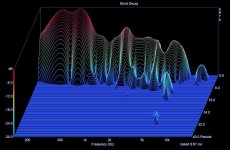
I don't know what that CSD is showing, there's nothing to compare infinite baffle response normalized to typical baffle response to determine diffraction influence.
Dave
That burst decay is taken in about 70cm distance from a self baffled
bending wave panel with dimensions approx 50cm x 100cm.
Microphone positioned in the center.
I cannot see any significant diffraction-reflections showing up in the
decay. When built into a box or a wall - maybe it would look a bit cleaner.
All of your points are made very well. I think we agree. But modeling the driver as accurately as you might think is necessary is largely beyond most DIY attempts. It's still reasonable to estimate the diffraction impact. The correlation with measured results can be very good without detailed driver modeling.Nothing to disagree about that. I did not even discuss minimum phase.
I talked about coherence and meant "arbitrary points on the membrane
moving with same amplitude and phase." Maybe the previous wording
was misunderstandable.
That lumped moving mass model is a common approximation at low
frequencies, neglecting any flexing or modal behavior of the cone.
Up to that point in discussion, we did not even include a more detailed
driver model. So i just remarked on the restricted validity of the lumped
model, when going towards higher frequencies.
At frequencies where the membrane shows vibrational modes,
estimation of baffle diffraction is fairly impossible without modelling
the driver.
This is why such - useful - tools like EDGE have a limited scope, which
is restricted to frequencies where "pistonic motion of the membrane
is a good approximation." Hopefully i now avoided misunderstandings.
Kind Regards
Dave
...
The correlation with measured results can be very good without detailed driver modeling.
Dave
I use tools like EDGE and i am rather statisfied. In fact for a floor
standing open baffle it may be far more important to take e.g.
floor reflections into account than try modelling the modal behavior
of the driver ....
Kind Regards
No, it is not nonsense. You seem to have totally misunderstood how software typically represents phase data on graphs. The inversion to which you speak is a physical impossibility and is not what is actually happening. Phase cannot invert at a point, your misunderstanding of the physics of drivers is apparent. The wrapping of the phase is nothing more than the phase being represented as a 360 degree graph rather than the continuously changing phase that actually occurs as it the phase actually goes beyond 360 degrees. It simply makes it easier to show on a limited range graph.
<snip>
Dave
REALLY? There is no software involved so what you say in again wrong. Try a little direct laboratory measurement for a reality check.
I never said phase flips at a point, phase flips over a very narrow band such as 1/10 of an octave or less. This occurs as the curve cone woofer changes mode from the cone moving (more or less) as a unit to where the inside moves positively and the rest of the cone moves negative. First "drum head" mode. This happens on every curved cone woofer. The transition bandwidth is very small. Indeed, those who use Fourier measurement methods will not see this unless the "bin" bandwidth is much smaller than the transition bandwidth. For loudspeakers IMHO Fourier analysis is almost useless unless the bin bandwidth is very small, say 1/512 root 2 progression or less.
dir, you are lost in the fallacies and assumptions of software and bogus models. There are many methods available which do not rely on software or some software hack's interpretation of methods and data. Try those "direct measurement methods" and discover reality.
As for the "error of the faulty premise," that is the number one obstacle for discovery and learning. Numbers two and three are the error of generalization and the error of specification. If you know nothing of logic or the logical process, would like to suggest everyone learn at least these three.
=SUM
Fallacy and bogus models? Empirical evidence shows otherwise and not just mine. Please do show your empirical data that contradicts. Phase can change over a narrow band, yes, but it's still minimum-phase, easily verified through correlation between measurements and, yes, models.dir, you are lost in the fallacies and assumptions of software and bogus models.
One cannot even show what the minimum-phase of a driver is (or is not) without an accurate model, since the absolute center cannot be precisely located and this therefore dictates that there will be some level of excess-phase left in measurement. The only way to verify minimum-phase (or not) is to compare and contrast measured phase with modeled minimum-phase. That is not debatable, but I suspect that you'll try.
In any case, I'll refer to someone much better able to describe the situation here. post 6633.
Dave
Last edited:
...
I never said phase flips at a point, phase flips over a very narrow band such as 1/10 of an octave or less. This occurs as the curve cone woofer changes mode from the cone moving (more or less) as a unit to where the inside moves positively and the rest of the cone moves negative. First "drum head" mode. This happens on every curved cone woofer. The transition bandwidth is very small.
....
Drivers having impedance maxima (resonances) within their
bandwidth and phase showing associated poles are quite common.
In this respect i can follow your observations with real drivers.
Nevertheless i assume the somewhat harsh tone between member
you and member dlr is at least partly due to some misunderstanding
concerning the term "minimum phase" system.
I am no electrical engineer but, as i understand it, systems
behaving like your description may still be minimum phase
systems as long as they have the smallest phase shift possible
due to their magnitude vs. frequency function.
If my assumption concerning this misunderstanding
- which in fact should not be my problem - should turn out right,
you could possibly shake hands and forget about the trouble.
😉
Last edited:
- Status
- Not open for further replies.
- Home
- Loudspeakers
- Multi-Way
- Measurements: When, What, How, Why