Wolfgang,
Would it be too much to ask for you to publish the exact winding specs for your transformers. I have found a really good source for cores and 2500 volt magnet wire. I would really like to try and make a set of these amps. I do not have the 20000 dollars necessary to purchase a 60 year old pair.
I had thought the robust Russian Gu-50 tube a nice candidate for this application. It seems that many of the large motor winding shops use the high voltage wire for the industrial motors and will sell it in less than truck load volumes.
Your cabinet layout and interior design is quite impressive I am sure you are proud of these amps. They will forever be one of a kind with quad differential output and all.
Tad
The original used 6LQ6 tubes, is there any particular reason these are not used today in other tube amplifiers ...?
Hi,
in the MC3500/MI350 amps one could use 6JE6C, 6LQ6 or 6MJ6 output tubes, which are almost equivalent. Unfortunately, more than 40 years after the amp has been developed, none of these are in current production, as for the purpose they once were designed for (colour tv sweep) they've become obsolete.
But I think, the 6KG6A/EL519 tube is a good replacement.
Best regards!
Last edited:
First amp modified
Hi Folks,
today I finished the modification of the first amp. So now both amps look like the same. Tests results with comuter based tests coming up in the next days. I use the "spectralab" software and an external sound interface.
The modifications are :
New front panel with only a single meter.
The potmeter and the switch are now based on a internal subchassis. So if the frontpanel has to be removed for repair work, the switch and the potmeter remain on the chassis. I must only remove the knobs.
The 4 capacitors C18-thru 21 are replaced against electrolytics with 150 mF.
A time delay for the overload protection to avoid the CB trips at high levels , especially at low frequencies. The CB trips at 2.2 Amp cathode , and at 350 mA screen grid current.
Meanwhile I get another 50 pcs 6p45S tubes. Now I have enough tubes for more testings.
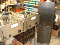
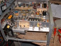
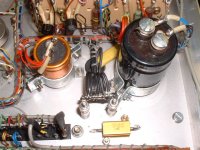
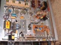
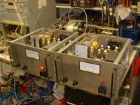
Here some pics of the amps. Now its 0400 h , local time. I go to bed now.
Thanks for interesting in my project!
73
Wolfgang
Hi Folks,
today I finished the modification of the first amp. So now both amps look like the same. Tests results with comuter based tests coming up in the next days. I use the "spectralab" software and an external sound interface.
The modifications are :
New front panel with only a single meter.
The potmeter and the switch are now based on a internal subchassis. So if the frontpanel has to be removed for repair work, the switch and the potmeter remain on the chassis. I must only remove the knobs.
The 4 capacitors C18-thru 21 are replaced against electrolytics with 150 mF.
A time delay for the overload protection to avoid the CB trips at high levels , especially at low frequencies. The CB trips at 2.2 Amp cathode , and at 350 mA screen grid current.
Meanwhile I get another 50 pcs 6p45S tubes. Now I have enough tubes for more testings.
Here some pics of the amps. Now its 0400 h , local time. I go to bed now.
Thanks for interesting in my project!
73
Wolfgang
Attachments


It seems from my research that there is not any other major amplifier design at Mcintosh which was designed by Milo except these superb Mc/Mi3500 amps. This is a great tribute to a talented designer in your efforts to clone his work. Kudos.
Could you please enlighten us to what choice of speakers you used to test your creation. Anything able to handle this much power must be quite nice.
I have often wished to build a pair of these Mcintosh legends but the major components are just too scare to source.
Please continue with this thread it contains volumes of historical information. And by the way the majority of the Mcintosh winders were elderly females with many years of experience. It also was one of the highest paying jobs at Mac.
Anyone with credible information which will help in unraveling the construction of these amps please chime in.
Thanks Tad
Unfortunately, Milo had a falling out with McIntosh. It got ugly and legal. The court favored with McIntosh. I occasionally wind the output for the MC3500. I have seen the original output transformer and it is quite cool it is made up of existing legacy parts from the McIntosh parts inventory...for example it uses the same cores as another very popular MC amplifier. It also uses the same wire gauge as another popular MC amp. All primary and secondary wire gauges are the same, one gauge for the entire transformer. Same turns per layer for both primary and secondary.
Chris
one gauge for the entire transformer
cerrem, can you tell me what gauge that was? thanks....
This is not a simple amp. Aside from being a rather large output transformer the specifics are unique indeed. No one else uses the output tube to transformer arrangement nor do they use the primaries and secondaries laying side by side. If an individual were to make up a set of simple construction plans for this amp DIY Audio may have another Aleph X length thread. It has been quite sometime since a project came together in the tubes forum like the Aleph X did in SS. Though many consider Mac to be just run of the mill with the prodigious feedback and such this amp is legendary. I am in.
Tad
Tad
I still have a couple of MC275 transformers to rewind, but in stead of the "original" ugly wound (that's why they shorted..) EI transformers I will restore the good old tradition by using c-cores.
These transformers however are different from MC3500 OPT's; they are bifilar wound for the primary plate and cathode sections, but not for the secondaries. I'd be in for a project, but IMO there is much to discuss.
These transformers however are different from MC3500 OPT's; they are bifilar wound for the primary plate and cathode sections, but not for the secondaries. I'd be in for a project, but IMO there is much to discuss.
Tony,
I completely took the transformers apart (also to see how they were wound...). The parts (EI laminates a.s.o.) are in a box. As pointed out these transformers had "bifilar" wound primaries, and secondary sections in between the primary sections. Because there was no interleaving/isolation between layers (also not between primaries and secondaries.....) the coil looked worse with every next layer.
You can start winding bifilar, but to wind a complete coil this way you must apply interleaving not to loose control. At the end the windings completely lost their "bifilarity". Yes as you call, the coil looked scramble wound, and that's why they failed (not impregnated - resonance - insulation break down).
thanks peter, i have more or less some picture of it in my mind now.....one last question, are those coils/traffo assembly set in the can using pitch or asphalt?
Transformers were potted in tar, which could be removed by heating the assembly on a kitchen cooker ...
I rewound output for MC3500 in South Africa back in 1970. I no longer have precise details but they did use a double C core and a single section bobbin. They were what I call random wound. SO the 5 wires were not perfectly vertical or horizontal but a more or less rope style bunch no twists though. Pitch had to be melted. Horrible, I used transformer wax for rebuild. Luxman also used pitch for all their transformers back then.
The EL509 is a very good approximation of the original 6LQ6. Yes 170 to 180 volt for screen is a good choice for either. Minus 40 to 55 volt bias is also reasonable.
Although tubes are in beam tetrode configuration, Due to the equal plate cathode coupleing. they operate in esentially cathode follower mode and are totally stable with no load. Too many preconceptions here.
All my current transformers I design are E I style. Plastic bobbins make for easy winding. McIntosh nailed his colours to C cores from the beginning early 1950s. Lots of copper and not much iron.
Hello all. I'm not new to this board but it is my first post so please forgive me if I'm clumsy. I've been building tube amps for 50 years and currently building a version of the MC3500 with some twists. My question is for 73 Wolfgang DF6ZC. I see in your pics two diagrams, one of impedance selection via toggle switches and the other looks like a winding chart. I'm wondering where you got these diagrams because they are not McIntosh data. I'm not implying that it wouldn't work but it's not what McIntosh wound. Is this what you made?
...my first post
> for 73 Wolfgang.... where you got these diagrams because they are not McIntosh data. ...
Welcome.
Did you miss the first page of the thread? The winding info seems to be all reverse-engineering between several members.
Attachments
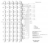
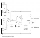
Thank you for your reply. I've read all the pages on this post but I can't tell where these diagrams came from. I have repaired MC3500's and MI350's in a past life and I know this is not how McIntosh wound the secondaries just by looking at the schematic printed on the OPT or the service manual. The secondary windings are what Daniel said 25th Feb, 2009 and Cerrem said 23rd Nov, 2011. I do understand how this winding scheme would satisfy 1,2,4,8 ohm loads but McIntosh didn't offer a 2 ohm output and did offer 50 and 64 ohm outputs which can't be achieved with this winding scheme. Also McIntosh didn't use toggle switches to select output impedance. So where did these two diagrams come from? Hats off to whomever figured them out.
- Home
- Amplifiers
- Tubes / Valves
- McIntosh MC-3500 Schematic Information