Hi,
since I got no information of the output section I design my own.
Te circuit with the 2 toggle switches ist easy to perform. And in real live I do not need to switch the speaker impedance over all day.
I had an aditional switch over for the four 27V windings to 108 V. I used this to operate 115V /400 Hz eqiupment on the speaker output , driven by an audio generator set to 400Hz.
But I haven´t already made a drawing from it.
At the very moment I got a another major problem , I had a fire in my house and I´m busy with restauration. Loads of my test equipment and material burnt to scrap. Me and some friends clear the cellar and brought 5 lorriers full of scrap to the scrapyard. The whole cellar is destroyed , no power, no gas , just the water supply is working. I got power from the neighbor and the oncoming week the gas supply and the fibre glas internet should be restored.
Luckily I can say my ground floor and the upper floor are only slighty damaged. It need only a thorough cleaning.
The firemens did a good Job.
So no time for fiddle about my amps.
73
Wolfgang
Wow, that's terrible, glad you are OK, and the loss is limited to the basement. Still very difficult to deal with I am sure!
Best of luck and I hope your home and life are sorted out soon.
Best of luck and I hope your home and life are sorted out soon.
Hi,
thanks for the sympathy. No way I will survive it. My lost equipment is replacable.
The workshop in he background of the pics are in my garage, so there is no damage , because it is a separate building..but without electricity by now.
I got a new (used) meter box and breaker panel from ebay , they are already fixed to the wall, need to be wired and the ok from the gridmaster. I hope the work goes fluently without any inconviencies.
The power company must replace the incoming fusebox. The box is property of the power company. It is toasted and the huge power cable is crisp at the surface. Its a 1,5 inch thick heavy duty four core cable. With bad luck they must digging a hole cut the end and replace it with a sleeve. That is the hardest part, espacially during the lockdown.
yes I did. I even wound the o/p transformers by my own. As I wrote , the amps working fine , I made them between 2009-2012. I got loads of worthful informations from members here at diyaudio.
73
Wolfgang
thanks for the sympathy. No way I will survive it. My lost equipment is replacable.
The workshop in he background of the pics are in my garage, so there is no damage , because it is a separate building..but without electricity by now.
I got a new (used) meter box and breaker panel from ebay , they are already fixed to the wall, need to be wired and the ok from the gridmaster. I hope the work goes fluently without any inconviencies.
The power company must replace the incoming fusebox. The box is property of the power company. It is toasted and the huge power cable is crisp at the surface. Its a 1,5 inch thick heavy duty four core cable. With bad luck they must digging a hole cut the end and replace it with a sleeve. That is the hardest part, espacially during the lockdown.
Did you make the winding chart yourself?
yes I did. I even wound the o/p transformers by my own. As I wrote , the amps working fine , I made them between 2009-2012. I got loads of worthful informations from members here at diyaudio.
73
Wolfgang
My very best wishes to you, Wolfgang! Glad you're healthy.
I'll comment on some postings later this evening.
I'll comment on some postings later this evening.
McIntosh
Dear Wolfgang,
Best wishes from us at Zed Audio. Pray that you can get your lab up and running soon.
BR
Stephen Mantz
Dear Wolfgang,
Best wishes from us at Zed Audio. Pray that you can get your lab up and running soon.
BR
Stephen Mantz
Dear Wolfgang, Thanks for your reply. Also very glad to hear you are alive and well in spite of the fire. I worry about fire myself. I heat partially with wood and have 5 fireplaces. Also I recently had to replace an electric baseboard 44 year old heater which threw sparks and blew a breaker. Hats off to you for the beautiful build, great work! I'm wondering where you learned the 5 primaries were 10 sections of 76 turns each.
Hi,
The magic word is patience. Since I fiddle with radio and electronics I wound my transformers succesful by my own.
It take a week to finish both transformers for these amps, day by day, 8h work.
73
Wolfgang
I'm wondering where you learned the 5 primaries were 10 sections of 76 turns each.
The magic word is patience. Since I fiddle with radio and electronics I wound my transformers succesful by my own.
It take a week to finish both transformers for these amps, day by day, 8h work.
73
Wolfgang
Hello Wolfgang. I wonder why you wound the primaries like McIntosh but you didn't wind the secondaries like McIntosh? Was it because you didn't need or want the 16 ohm, 50 ohm, and the 64 ohm output, or was it because you wanted the 2 ohm tap, or both reasons? Maybe some other reason?
Ron
Ron
Hi Folks,
today I finished the modification of the first amp. So now both amps look like the same. Tests results with comuter based tests coming up in the next days. I use the "spectralab" software and an external sound interface.
The modifications are :
New front panel with only a single meter.
The potmeter and the switch are now based on a internal subchassis. So if the frontpanel has to be removed for repair work, the switch and the potmeter remain on the chassis. I must only remove the knobs.
The 4 capacitors C18-thru 21 are replaced against electrolytics with 150 mF.
A time delay for the overload protection to avoid the CB trips at high levels , especially at low frequencies. The CB trips at 2.2 Amp cathode , and at 350 mA screen grid current.
Meanwhile I get another 50 pcs 6p45S tubes. Now I have enough tubes for more testings.
Here some pics of the amps. Now its 0400 h , local time. I go to bed now.
Thanks for interesting in my project!
73
Wolfgang
What is total output capacitors in microfarads
Ah! Why didn't you say so? The transformer impedences I can help you with. The primary has 5 windings, like Douglas said and are pentafilar wound. Each of these 5 windings has an impedence of 150 ohms end to end (ie. plate to plate, cathode to cathode, etc). The secondary has 4 windings, 2 have an impedence of 1 ohm, the other 2 have an impedence of 4 ohms, with a one ohm tap on them.
The transformer primary is wound in 10 sections with the secondaries in 8 sections interleaved between the 10 primary sections. They are wound like the original Williamson on 2 bobbins on a huge double "C" core. Each bobbin has "half" of the transformer on it; the 5 sections of one side of the primary interleaved with 4 sections of the secondary. I think, the center taps are the outer most winding on each coil (ie. the outer ends of the primaries are closest to the inner core of the bobbins with the center taps furthest away from the inner core). I hope this is understandable.
I have a pair of these transformers that I bought from a HAM radio operator. He bought a pair of these amps as surplus and only wanted the power transformers off of the amps; he scrapped the rest.
Anyway, the transformers are VERY heavy, probably about 75 pounds each. PL519's will work well if they are of good quality.
Hope this information helps...
Daniel
Keep in mind that the 8 ohm tap on this Output Transformer is actually a 9 Ohm tap, but they call it 8 ohms in the manual. Hint: When connecting a 8 ohm load to this 9 ohm tap, you drop the effective load to 108 Ohms on all 8 tubes. This now allows the power to extend higher to 350 Watts with 6LQ6 tubes.
The 470V dips to about 450V at full power and the screens are regulated at 180V but drops around 5V across the 200 Ohm screen resistor at full power output... So full power calculations are done at 450V Plate and 175V screen....of course there ia normal variance.
Also, due to the cost of the Quad coat wire they had to order in very huge quantities, this is one reason the MC outputs across the product line use the same wire gauge for everything, the other reason they used one small wire gauge for everything was for better packing density, thus more efficient wire packing, they just parallel as many wires together as needed to get the required circular mills needed...this also avoids any skin effects when using many smaller insulated wires in parallel, the secondary also was done in the same small wire gauge. All secondary section were also paralleled. When using the same wire gauge the layer to layer build is more even and smooth and not lumpy which also would waste packing space.
cerrem
Thank you for your reply. I've read all the pages on this post but I can't tell where these diagrams came from. I have repaired MC3500's and MI350's in a past life and I know this is not how McIntosh wound the secondaries just by looking at the schematic printed on the OPT or the service manual. The secondary windings are what Daniel said 25th Feb, 2009 and Cerrem said 23rd Nov, 2011. I do understand how this winding scheme would satisfy 1,2,4,8 ohm loads but McIntosh didn't offer a 2 ohm output and did offer 50 and 64 ohm outputs which can't be achieved with this winding scheme. Also McIntosh didn't use toggle switches to select output impedance. So where did these two diagrams come from? Hats off to whomever figured them out.
It appears to be a real PITA to disassemble such a transformer. Melting the tar, keeping the transformer package hot enough for some time to get as much tar dripping off it as possible etc. Did anyone do it yet? Really?
Trying to put together relevant informations from these postings and distillate some questions and conclusions:
I don't think the fill factor within a winding can be increased by chosing thinner wire if the same diamater wire is used all the time. Think of a square with a circle that fits into it. The relationship between the square's and the circle's areas is the same as if you'd put four circles that fit well into the square's corners.
Anyway, the DC resistance info means that the cathode and plate windings are wound with four parallel wires and the three others with single wires. Is this correct, and if so, were the eleven wires stranded before winding?
Unfortunately the MC3500 schematics shows the impedance selector as a black (white, actually) box. So we don't know what it really does. Given there are only 1 ohms and tapped 4 ohms secondary sections, how can an output impedance of one ohm be achieved besides not connecting the four ohms parts, hence with reduced efficiency? And how can 50 ohms be realized?
The transformer's weigth of 70 pounds is quite some number. How is the whole unit's weighth then, as there are two more transformers, the electronic components inside and the heavy chassis also?
I think Wolfgang has done a workaround by calculating with his given cores. And he did it well. Apparently his intention never was to clone the MC as close as possible, but to create a unit that is useful enough to himself. For this instance I'd also restrict to output impedances of 4, 8, and 16 ohms. Using 1 ohms sections, a three position five pole switch or five double throw relays plus a logical (diode) matrix would be needed to achieve this.
Another option would be adding a pair of 0.7 ohms packs. This would allow for real 8 ohms and reduce the impedance switch to a three position three pole one.
Best regards!
Hi Folks,
wow, another year passed by with huge steps. I can´t believe it. My repair works on my house go on. I got a new kitchen, my office is already paint , got eletricity and is online with a new fibre optic internet with 250Mbit/sec. and the central heating works
My living room need to be paint. A friend promise will help me , paintwork is not my job.
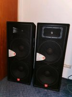
And finallay I got my McIntosh replicas into my living room. And had several soundchecks . I´ve got a pair of JBL JRC225 2x15" PA Speaker, they not ideal for home listen. But at first it is better than nothing. My JBL control 12 cannot handle the amont of power , i´m fear of damage them inadvertently, by cranking up AC/DC tunes.😀
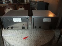
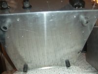
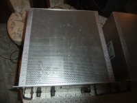
I finished the amps by fitting a cover and a bottom plate with rubber feets.
I recently got a load of unused 6P45s tubes , sold by a widow of a silent key. Now I hold a stock of abt 160 tubes. enough for a long, long amp life. 😀
I will make a suitable pair of speaker by my own with the help of my nighbor. I´m not good in woodwork . But it will go on when all the renovation is finished. Until then the JBLs are there to blow the windows out . I use the JBLs normally for outdoor activities in my nighborhood
My 1500W GU-81 project ist also on suspension. The second amp is nearly finished.
Here a the pics with cover and bottom
from left to right:
JBL PA bins, both amps side by side, bottom with feets, cover from perforated aluminium sheet.
73
Wolfgang
wow, another year passed by with huge steps. I can´t believe it. My repair works on my house go on. I got a new kitchen, my office is already paint , got eletricity and is online with a new fibre optic internet with 250Mbit/sec. and the central heating works
My living room need to be paint. A friend promise will help me , paintwork is not my job.
And finallay I got my McIntosh replicas into my living room. And had several soundchecks . I´ve got a pair of JBL JRC225 2x15" PA Speaker, they not ideal for home listen. But at first it is better than nothing. My JBL control 12 cannot handle the amont of power , i´m fear of damage them inadvertently, by cranking up AC/DC tunes.😀
It sound as exspected , my room has a self resonance at 35Hz. So its too much rumble , but me and a mate work on a solution.I finished the amps by fitting a cover and a bottom plate with rubber feets.
I recently got a load of unused 6P45s tubes , sold by a widow of a silent key. Now I hold a stock of abt 160 tubes. enough for a long, long amp life. 😀
I will make a suitable pair of speaker by my own with the help of my nighbor. I´m not good in woodwork . But it will go on when all the renovation is finished. Until then the JBLs are there to blow the windows out . I use the JBLs normally for outdoor activities in my nighborhood
My 1500W GU-81 project ist also on suspension. The second amp is nearly finished.
Here a the pics with cover and bottom
from left to right:
JBL PA bins, both amps side by side, bottom with feets, cover from perforated aluminium sheet.
73
Wolfgang
Attachments

resurrect that GU81m project. I gave up on a 350W Class A amp around them... 🙂 Now what to do with a half dozen and a quad of sockets. A g2-as-anode comes to mind; there is more dissipation there than an 813 has on its plate.
Douglas
Douglas
Last edited:
Hi Wolfgang,
perhaps you may want to build JBL 4435 clones, which definitely can cope with 350 Watts from your MC-3500's? It might perhaps be somewhat difficult to source the drivers, but you can make 2234H's from 2225 baskets and C8R2235 cone assemblies (or aftermark clones of these), and I might help you with 2234 or 2234A horns and 2421A, 2425J or 2426J compression drivers. The xover network schematics is available via the WWW.
Best regards!
Hi Kay,
Yes, the JBL44 series are neat speakers. If you find a pair on ebay they go for several thousand bucks. This project has to wait until I got the money for it.
Hi Douglas,
here are some pics of the GU81 1500W p-p Amp I made. This is #1 the second amp is already in process.
The thread:
https://www.diyaudio.com/community/threads/gu-81m-tube-amp-schematics.183163/page-7#post-6246888
perhaps you may want to build JBL 4435 clones,
Yes, the JBL44 series are neat speakers. If you find a pair on ebay they go for several thousand bucks. This project has to wait until I got the money for it.
Hi Douglas,
here are some pics of the GU81 1500W p-p Amp I made. This is #1 the second amp is already in process.
The thread:
https://www.diyaudio.com/community/threads/gu-81m-tube-amp-schematics.183163/page-7#post-6246888
- Home
- Amplifiers
- Tubes / Valves
- McIntosh MC-3500 Schematic Information