With the regulated -165V I,ll not agree with you. If I use a stabilized Vg1 theres is no compensation angainst mains variation. Unreg. Vg1 means, mains voltage rise, means increasing of +B ; means more idle current. So in this way Vg1 increase also compansate the increasing idle current.
Regulated Vg1 make only sense in a circuit with regulated +B.
Dear Wolfgang,
please pardon my jumping in, but I'm fascinated on your work ;-)!
Sorry, but I don't agree with your statement. As we know, in a tetrode/pentode anode current is mostly by far influenced by grid voltage, followed, in the ratio of 1/µg2g1, by screen voltage, whereas anode voltage has nearly no influence on it. Thus, variations of means voltage are quite a little bit compensated, as the absolute values of grid and screen voltages vary in the same ratio. As a remains, anode current varies by: ΔIa = ΔUg1/ΔUg2 * µg2g1. (Sorry, but I don't manage posting Greek letters...)
I don't want to complain on Mile Nestorovic's great overall design, but regulating screen voltage and leaving grid and anode voltages floating, is worst case scenario with respect to anode current stability, even worse than leaving all voltages unregulated! It is much better to regulate grid voltage and leave all other voltages floating. When considering to regulate voltages at all, we basically should regulate screen and (!) grid voltages. Best results, of course, are given by regulating all voltages.
As you know by our mail correspondence, I'm also tinkering with the idea of building these amps, somewhat downgraded by using only four final valves (6KG6A). But instead of the heavy, bulky and costly power trannies, my amps will be provided with SMPS, thus giving regulation of all voltages, as aforementioned.
We shall see...
Best regards!
Sorry, folks, but I have to stand corrected with my formula...
Well, here we go again:
But we also see the big influence of ΔUg1, if Ug2 is regulated, i.e. constant, and the minor influence of ΔUg2, if Ug1 is regulated.
Best regards!
Well, here we go again:
ΔIa = Ia0 * gm (ΔUg1 + ΔUg2/µg2g1) (Yippie, I've managed to type at least some greek letters  !)
!)
Given an unregulated power supply, we can say: !)
ΔUg1 ~ Ug10 and ΔUg2 ~ Ug20
As in most cases Ug1 is negative, and Ug2 is positive, variations in both, caused by floating means voltages, counteract. So we should expect perfect compensation, if Ug2 = Ug1 * µg2g1. Very unusual, I think...
But we also see the big influence of ΔUg1, if Ug2 is regulated, i.e. constant, and the minor influence of ΔUg2, if Ug1 is regulated.
Best regards!
Only one wire gauge is used for the entire transformer....primary and secondary.....
It's a matter of paralleling the windings to get the current density needed....
Chris
Hi Chris,
according to Dan's measurements, which I do not disbelieve, this would mean that McIntosh would have wound no less than eleven wires at once for the primaries (four in parallel for cathode, also four for anode, and one each for screen, feedback and bootstrap windings). Do you really believe this?
Another question@all: As the primary halves are intersected in five sections each, how are they finally connected? Do we find all five sections wound on one bobbin (or in one chamber) and put together in series, or are sections #1,3 and 5 on one bobbin and sections #2 and 4 on the other?
Best regards!
Truely outstanding work Wolfgang🙂
Could you repost some pictures of the completed output transformers you had in post 14?
Also, where do you get or what is the type/manufacturer of the wire you used for the multifilar windings? I ask because I have a whole bunch of Wassner C-cores and have thought of winding a unity coupled type transformer. I have thought of using Kynar wire but because of the insulation thickness it makes it almost impossible to design a sensible transformer.
I just had a google about on the MC-3500 and found this site:
MC-3500
If you scroll down a bit it has some original Mac promotion material stating that when used with low efficiency speakers such as the Bose 901 they recomend a fuse for the speaker. Would failure of this fuse surely not put the insulation of the output transformer in serious trouble? It would blow at high power and the voltage accross the primary would soar until insulation breakdown. Just wonder if that is indeed ok with the Mac output transformer?
Oh, we have some German markets over here at this time of year and they have some excellent beers😀
Cheers Matt.
Hi Matt,
me again. I ask the manager of the trafo company about the wire he sold to me.
It is double insulated enamelled copper wire , made by "Synflex" W210
Synflex Elektro GmbH: Enamelled Copper Wire Type W 210
The link bring you direct to the manufacturers data sheet, it is available in english.
The wire withstands 750V rms and it is tested with 2400 Volts. The max. operating temperature is 210 degree centigrade. You should get the wire in England at any motor/ trafo winding shop as England is traditional big in trafo and motor production.
There are much better wires obtainable for this kind of transformer. But they are twice as much in price than this wire , eg spun wires, normally use for high voltage transformers such as for high power transmitters. These wire are need more space on the bobbin.
regards
Wolfgang
DF6ZC
Thank you very much Wolfgang😀
Cheers Matt.
Hello Wolfgang, I just had a thought about your oscillation at power off. My prototype AB2 amp oscillated at around 800 Khz after switch off. It turned out to be the bias supply disappearing before the main B+ because the main capacitors hold a charge for a few seconds after switch off. This caused the output valves to be biased on really hard for a couple of seconds. I fixed it by sequencing the supplies at switch on and off.
Cheers Matt.
Cheers Matt.
Hello Wolfgang, I just had a thought about your oscillation at power off. My prototype AB2 amp oscillated at around 800 Khz after switch off. It turned out to be the bias supply disappearing before the main B+ because the main capacitors hold a charge for a few seconds after switch off. This caused the output valves to be biased on really hard for a couple of seconds. I fixed it by sequencing the supplies at switch on and off.
Cheers Matt.
Hi Matt,
thanks for this idea. I will do it another way. I will try it out first with an greater capacitor on -C voltage . At the moment I use 80µF. So I will hook a 470µF makeshiftly parallel to the 80µF . The mechanical outline of both capacitors are quite similar. If it works I will fit the 470µF proper in the clamp instead the now existing 80µF.
In this circuit the -C Voltage is also a part of the operating voltage for the driving kath. follower. So the -C will be loads with about 15mA . The +B remains abt. 5 seconds until it drops below 150V.
73
Wolfgang
DF6ZC
Hi Chris,
Another question@all: As the primary halves are intersected in five sections each, how are they finally connected? Do we find all five sections wound on one bobbin (or in one chamber) and put together in series, or are sections #1,3 and 5 on one bobbin and sections #2 and 4 on the other?
Best regards!
Hi there,
In my original post I may have misled people by saying that the coils were wound on two bobbins; they are on one bobbin that is split down the middle. Take a look at Funker's pictures where he is showing the assembly of the transformer. Look at the picture that clearly shows the bobbin. see how it is divided in the middle? I had further correspondance with him before he made the transformers, so he got the idea that I was trying to convey.
Also, take a look at Williamson's notes on output transformer manufacture. This is where McIntosh got the idea for winding their transformers, but used "C" cores instead as they would give a better quality finished product.
So, on each "half" bobbin, there are 5 sections of primary (wired in series, end to end) interleaved with 4 sections of secondary, which are wired in parallel.
I also did not understand Cerrem's statements about which only one gauge of wire was used but wired in parallel to get a smaller effective gauge number. This could have been done as most of Mcintosh's output transformers were wound in complicated geometries... They had VERY good transformer winders at that factory!
Hope this helps....
Daniel
Dan,
I have taken this transformer apart and rewound one back in 1996. I have also made a few repros of this output for some amp builders. So the hints I am passing along are not pulled from my A$$. The bobbin is a plain single bobbin with no split. .The bobbin is made from thin piece of folded fish paper and provided no support to the windings, only keeps it electrically insulated from contacting the double C-cores. The transformer is assembled in the following manner.
A aluminum madrel is used, they fold the fish paper around the madrel, they spin the wire, all the same wire gauge for primaries and secondaries. Then it is terminated to a small phenolic board with lead wires. then a few layers of tape to hold the paper bobbin to the coil, transformer is then lightly varnished then the mandrel is removed and the two C-cores are installed and banded.
Another hint, the cores and wire used were already in inventory because it was already used on other popular MC tube amps..Using what they already had instead of making new order of materials. The primary sections is not 5 and secondary sections are not 4. I have not seen any MC output transformers that share any similarity with the Williamson output transformer methods, and I have rewound just about all the popular MC outputs.
Chris
Last edited:
Hi Chris,
"Primary is in 10 sections and interleaved with 8 sections of secondary"...
I got that from the MC-3500 Owners or Service manual, I cant remember which. No, I have not unwound any of these transformers, but I did take measurements of the windings and each primary winding from CT to each end has exact measurements; IE. They are not only inductively balanced but also electrically balanced. Peerless did this with a lot of their output transformers which I know were wound like the Williamson outputs. In fact, it's the only way I can think of where each half of the primary is an exact match to the other half, both inductively and electrically.
Anyway, The original info I gave Funker was what I thought to be accurate at the time and he made a transformer that performs close to if not equal to the original MC3500 / MI350 outputs.
Daniel
ALthough most multi-filar transformer windings are "Side-by-Side" wound..which puts the wire strands horizontal to each other....There is another way to wind multi-filar strands and that is so they are VERTICAL to each other. This means that within a single PRIMARY section of say 5 layers...The first layer is Plate, second layer is Cathode, third layer is driver winding, etc.
This is vertical layering of the penta-filar. Now take it a step further...suppose you Bi-Filared each layer, meaning 2 strands for plate, 2 strands for Cathode, 2 strands for driver, etc. If you then take each of the two strands on each layer and apply it to each side of the Push-Pull you would now have symmetrical DC resistance in addition to AC symmetry. This adds another benefit, you now have lower leakage inductance from primary half to primary half, which is just as important as having low leakage inductance from Primary to Secondary. You also lower the primary to primary self winding capacitance since there is no AC wiggle between these two bi-filared halves if you hook them up properly, but such capacitance reduction is of little advantage with such a low unity coupled impedance.
Keep in mind that this transformer winding has NO interleaving material between the Primary and Secondary only the wire coating is protection...this needs to be very good triple or Quad coat wire.
One other interesting thing about the MC3500 output transformer, it breaks the Golden Rule that McIntosh based his transformer off of. The screen supply is now regulated, this creates a non-linearity unless the cathode is grounded. Since past MC outputs have the SCREEN winding AC floating with the CATHODE winding, this keeps a CONSTANT SCREEN to Cathode potential during dynamic operation which keeps the gm locked in steady, when the gm is steady then the tube behaves more linearly.
Chris
Last edited:
Hi Chris,One other interesting thing about the MC3500 output transformer, it breaks the Golden Rule that McIntosh based his transformer off of. The screen supply is now regulated, this creates a non-linearity unless the cathode is grounded. Since past MC outputs have the SCREEN winding AC floating with the CATHODE winding, this keeps a CONSTANT SCREEN to Cathode potential during dynamic operation which keeps the gm locked in steady, when the gm is steady then the tube behaves more linearly.
Chris
have a closer look at the schematics and see that screen supply comes from a regulated DC voltage (+180V), then goes through a supplementary primary winding of the output (3rd from left) which AC couples it to the respective cathodes. Thus true pentode operation of the output valves is obtained - as it is in each other McIntosh unity coupling design.
Cheers!
Agreed, Steve!I would remove the cathode follower input completely and inject the input signal directly at the R9-R12 junction. No need for the cathode follower. My MI350s have a full constant current driver for the cathodes of the cathode follower and both sections of the ECC83 are paralleled.
I'm also wondering about the necessity of this cathode folower as an input stage, especially due to the high input impedance of the following LTP phase inverter - and to the 56 kΩ resistor in the grid line of the second valve. Any ideas?
Best regards!
Hi all.
I did some variations , one of them was to override the R12 /56k. The result was a nice oscillation of abt 500 kHz. The same with R17.
All these measures with the components R12,R17, C5,C6 C7, C9 are in need for Phase corrction and RF-self oscillation protection. I have to changed the value of C9 and C7 due to my homebrew transformer. I replaced them against trimmer cap and adjusted to best square wave behavier.
The input kath. follower is to drive V10 upper half due to grid current with high input levels. Normally the input impedance is relativ high. But with high input levels V10 go into the grid current mode. The grid of V10 is biased with only 0.9 Volts. The peak input level is abt. 3V pp.
If the amp is driven from a low impeance sources like an Studio mixer the kath. follower can be omitted. But in those days where the amp was developed the output impedances of preamps was quite high as 100 k Ohms.
By the way I finished the main frame for the second amp🙂.
73
Wolfgang
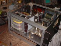
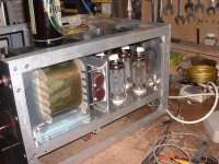
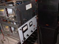
Second Amp Mechanically Finished
Hi All,
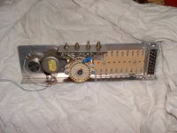
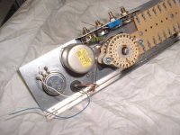
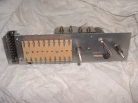
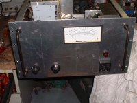
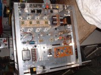
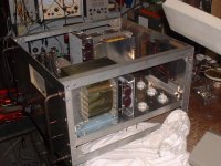
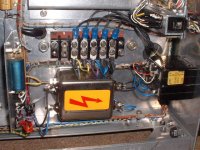
today I finished the mechanical work of the second amp. I changed the layout of the meter switch ***´y and the meter itself. If the front panel has to be removed for service, the meter switch and the potmeter remain on the chassis . So not by the first amp. The potmeter and the switch are fixed at the front panel. If the front panel is disassembled the switch and potmeter dangling from the chassis and its easy to manage to be zapped while working on the amp. Furthermore the whole switchass´y is fitted on a removable plug-in unit for easy access. I will rebuilt the first amp like this.
The reason to use different meters is simple as I cannot hold of a set of these old meters. Even I like the old style but no meters.... This meter replace the two others. It indicate the output power level, Vmains, Vg1, Vg2, Vplate and the idle current of all 8 output tubes.
There are also little bits and pieces which are different from the first one, all will be transfered to the first one. The protection board and the voltage amp are already wired and tested.
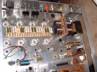
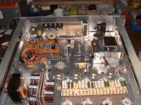
Now I will start with wire harness . If everything goes well the amp will be finished in a couple of weeks. In the attachment are some pics.
73
Wolfgang
Hi All,
today I finished the mechanical work of the second amp. I changed the layout of the meter switch ***´y and the meter itself. If the front panel has to be removed for service, the meter switch and the potmeter remain on the chassis . So not by the first amp. The potmeter and the switch are fixed at the front panel. If the front panel is disassembled the switch and potmeter dangling from the chassis and its easy to manage to be zapped while working on the amp. Furthermore the whole switchass´y is fitted on a removable plug-in unit for easy access. I will rebuilt the first amp like this.
The reason to use different meters is simple as I cannot hold of a set of these old meters. Even I like the old style but no meters.... This meter replace the two others. It indicate the output power level, Vmains, Vg1, Vg2, Vplate and the idle current of all 8 output tubes.
There are also little bits and pieces which are different from the first one, all will be transfered to the first one. The protection board and the voltage amp are already wired and tested.
Now I will start with wire harness . If everything goes well the amp will be finished in a couple of weeks. In the attachment are some pics.
73
Wolfgang
Attachments
-
 meter-switch-assy-1.JPG57 KB · Views: 583
 -
 meter-switch-assy-5.JPG62.2 KB · Views: 248
 -
 meter-switch-assy-2.JPG54.7 KB · Views: 252
 -
 Bottom-view-1.JPG86.7 KB · Views: 281
 -
 Fron-panel-view-1.JPG58.2 KB · Views: 272
 -
 Bottom-inside-without-meter-assy-1.JPG81.2 KB · Views: 575
 -
 Bottom-inside-with-meter-assy-1.JPG85.5 KB · Views: 582
 -
 Front-right-view-1.JPG64.8 KB · Views: 587
 -
 Front-left-view-1.JPG66.8 KB · Views: 590
Hey Wolfgang,
I am sorry I have not been in contact before now. I have had a hectic couple of months, spent Christmas in Rome, got engaged to be married etc.
You have been really busy with your builds! Absolutely excellent work!!
Do you think the toggle switches for output impedance selection will be reliable enough? I think that as they will not be switched regularly they may become intermittent. Perhaps a rotary type switch with wiping contacts would be a better selection?
cheers Matt.
Last edited:
Toggle switches
Hi Matt,
these toggles are military grade, salvaged from a scraped Racal Transmitter. They are specified for 15 Amps and 250 Volts. They working perfect in the first amp.
It is no problem with the short interruption of the current path while flip them over. In a normal situation you operate the switch with the amp off or with no signal driven. And also to avoid inadvertently operating, these switches are flush mount. To operate them it requires a tool, a screwdriver etc.
A rotary switch can shorten all terminals while turn it in the other position. If the amp operate at higher output levels while turning the switch, the short circuit currents can damage the contacts.
Every solution has its own ifs and whens. In my opinion the toggle switches are a good an affordable solution. First I´m considered to use a rotary switch to set all possible output impedances from 1,2,4.8,16 Ohm and 100V line.
Yes believe or not I made such a kind of switch from the part of many other old rotaries. But this take to much space beneath the chassis. So I turn to the toggle version. 1 to 8 ohms are enough variations.
Thanks for the hint.
73
Wolfgang
Second Amp Finished
Hi ,
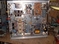
yesterday I finished the second amp with the wiring. Today I made different testings. I´d miswired accidently the socket of V14 , the driving tube. I confused grid and cathode of one system. And another fault was I forgetting 2 wires at the terminal board of the opt.
After this I checked all voltages on the tube bases before I plugged the tubes in. And than the big moment, I had the plate xfmr connected via an varac to the mains terminals. So in this way I can slowly increase the plate volts and the CB is still in the line. I turned up the voltage after the tube were preheated. Bugger 😡! The amp starts oscillate near full plate volts.
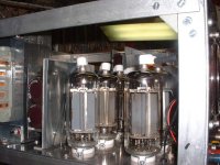
The RF-ferrite plate choke of the upper row of the 4 finals heats up and left a smell of burned wire insulation. I changed the 4 tubes of the upper row and Bingo, the oscillation stops. Now I set the plate idle current to 50mA . It looks good , but when I apply a input signal , the amp was unstable and generate rf-bursts. At this time, first a cup of tea and took a look into the wiring. If the there is a 4,7k resistor to fit, I should install a 4,7k and not a 4,7 meg.
After replacing this slightly off rated part.😀, the amp work like he shall work🙂
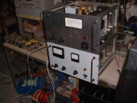
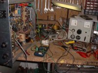
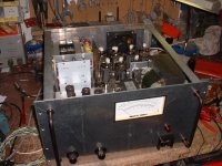
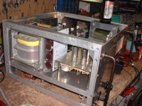
I will find out later whats the hell are wrong with the tubes of the upper row. The output power is the same like the other amp the amp delivers 450W into 4 Ohms at stabilized 230V AC mains. I listen to it together with the first amp. Absolute bloody marvelous sound. The driving amp was my makeshift preamp (upper row, right pic). It is a breadboard version of next project. Here some pics.
The next step is to rebuild the first amp,that they both looks the same.
73
Wolfgang
Hi ,
yesterday I finished the second amp with the wiring. Today I made different testings. I´d miswired accidently the socket of V14 , the driving tube. I confused grid and cathode of one system. And another fault was I forgetting 2 wires at the terminal board of the opt.
After this I checked all voltages on the tube bases before I plugged the tubes in. And than the big moment, I had the plate xfmr connected via an varac to the mains terminals. So in this way I can slowly increase the plate volts and the CB is still in the line. I turned up the voltage after the tube were preheated. Bugger 😡! The amp starts oscillate near full plate volts.
The RF-ferrite plate choke of the upper row of the 4 finals heats up and left a smell of burned wire insulation. I changed the 4 tubes of the upper row and Bingo, the oscillation stops. Now I set the plate idle current to 50mA . It looks good , but when I apply a input signal , the amp was unstable and generate rf-bursts. At this time, first a cup of tea and took a look into the wiring. If the there is a 4,7k resistor to fit, I should install a 4,7k and not a 4,7 meg.
After replacing this slightly off rated part.😀, the amp work like he shall work🙂
I will find out later whats the hell are wrong with the tubes of the upper row. The output power is the same like the other amp the amp delivers 450W into 4 Ohms at stabilized 230V AC mains. I listen to it together with the first amp. Absolute bloody marvelous sound. The driving amp was my makeshift preamp (upper row, right pic). It is a breadboard version of next project. Here some pics.
The next step is to rebuild the first amp,that they both looks the same.
73
Wolfgang
Attachments
-
 3500-Front-left-view-1.JPG82 KB · Views: 286
 -
 3500-ropt-tubes-1.JPG69.1 KB · Views: 260
 -
 3500-both-amps-fronr-1.JPG61.7 KB · Views: 220
 -
 3500-both-amps-working-1.JPG59.9 KB · Views: 250
 -
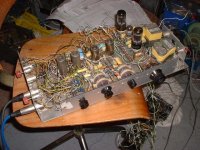 makeshift-preamp-1.JPG85.9 KB · Views: 245
 -
 3500-underneath-mains-section-1JPG.JPG86 KB · Views: 207
 -
 3500-underneath-1.JPG88.8 KB · Views: 209
 -
 3500-testing-1.JPG84.1 KB · Views: 235
 -
 3500-Front-view-1.JPG67.1 KB · Views: 264
 -
 3500-Front-right-view-1.JPG80 KB · Views: 241
It seems from my research that there is not any other major amplifier design at Mcintosh which was designed by Milo except these superb Mc/Mi3500 amps. This is a great tribute to a talented designer in your efforts to clone his work. Kudos.
Could you please enlighten us to what choice of speakers you used to test your creation. Anything able to handle this much power must be quite nice.
I have often wished to build a pair of these Mcintosh legends but the major components are just too scare to source.
Please continue with this thread it contains volumes of historical information. And by the way the majority of the Mcintosh winders were elderly females with many years of experience. It also was one of the highest paying jobs at Mac.
Anyone with credible information which will help in unraveling the construction of these amps please chime in.
Thanks Tad
The original used 6LQ6 tubes, is there any particular reason these are not used today in other tube amplifiers ...?
No one makes 6LQ6's anymore, and the CB and Ham operators used them all up, so they are very expensive now. Any product would deplete the remaining few stock.
Speaker driven with the MC-3500 clone
Hi Tad,
thanks for your comment. It was a long lasting task to build them. But I like to do so and will do it always again...
I using not such a kind spectacular speakers as you may think I would use.
Every amp drive a JBL control 12 and a old PA/ reinforcement Speaker , fitted with 8 ea 5 inch fullrange chassis of total 150 rms / 300W music peak power handling.
It took 3 days to wind the both bobbins and a total of a week for fiddle all the 144 wire ends together and the final completion of core, bobbin and testing. After that I had blisters on my fingers.
73
Wolfgang
Hi Tad,
thanks for your comment. It was a long lasting task to build them. But I like to do so and will do it always again...
Could you please enlighten us to what choice of speakers you used to test your creation. Anything able to handle this much power must be quite nice.
I using not such a kind spectacular speakers as you may think I would use.
Every amp drive a JBL control 12 and a old PA/ reinforcement Speaker , fitted with 8 ea 5 inch fullrange chassis of total 150 rms / 300W music peak power handling.
And by the way the majority of the Mcintosh winders were elderly females with many years of experience. It also was one of the highest paying jobs at
It took 3 days to wind the both bobbins and a total of a week for fiddle all the 144 wire ends together and the final completion of core, bobbin and testing. After that I had blisters on my fingers.
73
Wolfgang
- Home
- Amplifiers
- Tubes / Valves
- McIntosh MC-3500 Schematic Information