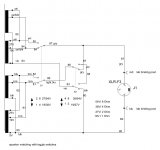
To clarify the secondary windings. There are two windings that are 1 ohm....and there are two windings that are 9 ohms that have 4 ohm taps or depending which way you view it you can say 1 ohm taps. When you take a 4 ohm winding and add a 1 ohm winding to it you get a 9 ohm total result for the full winding.
cerrem
cerrem
Hi all,
@ke4mcl
The valve I used , the russian 6P45S is also a TV horizontal output tube. It is similar to the european EL519 / PL519 , the different between the P or E type is the heater. The E is 6,3V and the P is for 300mA serial operation. The 6P45S is one of the strongest valve with its 45W plate dissipation and 1,2A max kathode current.
@ Steve Manz
At first I like to get the amp working close to the original performance. If everthing is proper working I will start the improvement with CCS and so on.
The only thing what I made not like the original is my own safety circuit design and the screen grid regulator.
@ cerrem
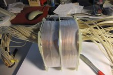
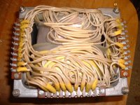
I made the secondairies to my own speaker impedance seletor. Since the original speaker switch is hard to get I considered a design which employ only 2 standard toggle switches . I made the secondairies in this way . I hope the drawings are readable. The toggle switches selcet between 1 / 4 Ohms and 2/8 Ohms
here are the drawing:
@ Daniel Frank
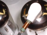
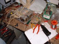
I inserted also some little chokes into the plate leads. I helps but not in the way as I respected. So I put another little ferrite bead on every plate lead, that make the amp much more stable. After spending many more hours in my workshop, I try several ways to fight the parasitic oscillation. The capacitor C / , 39 pF is one of the phase correction device .I disconnected this to see what happened without it, and bingo the oscillation stops. McIntosh wouldn't fit a capacitor like C7 without any reason. What is the real reason for C7? Another improvement was to get the wires from the test meter switch out of the harness and put them through another route to the cathode resistors and point A and B.
see the beads on the thick black plate leads:
and here are my homemade plate chokes:
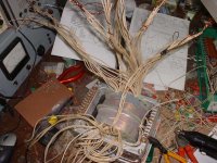
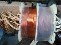
The wire I used to wind the primaries are 0.375 mm for feedback, bootstrap and screens and 0.75mm for plate and kathode. The wire is a special one which is used to wind high voltage Motors with for the 700 and 1500 Volt industrial mains. The secondaries are wound with 1.06 mm wire. Sorry I can´t find a AWG conversations table.
here a pic winding one of the primary:
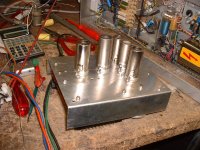
Here are some more pics.
the core:
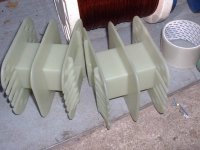
The coil former:
the coil:
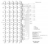
the transformer schematic:
Thanks all for the interest in my project.
regards
Wolfgang
@ke4mcl
The valve I used , the russian 6P45S is also a TV horizontal output tube. It is similar to the european EL519 / PL519 , the different between the P or E type is the heater. The E is 6,3V and the P is for 300mA serial operation. The 6P45S is one of the strongest valve with its 45W plate dissipation and 1,2A max kathode current.
@ Steve Manz
At first I like to get the amp working close to the original performance. If everthing is proper working I will start the improvement with CCS and so on.
The only thing what I made not like the original is my own safety circuit design and the screen grid regulator.
@ cerrem
I made the secondairies to my own speaker impedance seletor. Since the original speaker switch is hard to get I considered a design which employ only 2 standard toggle switches . I made the secondairies in this way . I hope the drawings are readable. The toggle switches selcet between 1 / 4 Ohms and 2/8 Ohms
here are the drawing:
An externally hosted image should be here but it was not working when we last tested it.
@ Daniel Frank
I inserted also some little chokes into the plate leads. I helps but not in the way as I respected. So I put another little ferrite bead on every plate lead, that make the amp much more stable. After spending many more hours in my workshop, I try several ways to fight the parasitic oscillation. The capacitor C / , 39 pF is one of the phase correction device .I disconnected this to see what happened without it, and bingo the oscillation stops. McIntosh wouldn't fit a capacitor like C7 without any reason. What is the real reason for C7? Another improvement was to get the wires from the test meter switch out of the harness and put them through another route to the cathode resistors and point A and B.
see the beads on the thick black plate leads:
An externally hosted image should be here but it was not working when we last tested it.
and here are my homemade plate chokes:
An externally hosted image should be here but it was not working when we last tested it.
The wire I used to wind the primaries are 0.375 mm for feedback, bootstrap and screens and 0.75mm for plate and kathode. The wire is a special one which is used to wind high voltage Motors with for the 700 and 1500 Volt industrial mains. The secondaries are wound with 1.06 mm wire. Sorry I can´t find a AWG conversations table.
here a pic winding one of the primary:
An externally hosted image should be here but it was not working when we last tested it.
Here are some more pics.
the core:
An externally hosted image should be here but it was not working when we last tested it.
The coil former:
An externally hosted image should be here but it was not working when we last tested it.
the coil:
An externally hosted image should be here but it was not working when we last tested it.
the transformer schematic:
An externally hosted image should be here but it was not working when we last tested it.
Thanks all for the interest in my project.
regards
Wolfgang
Last edited:
Use the forum photo app, it works so much better, really.. 😀
Not to mention in a year or two when someone comes looking for this thread all of the pictures will be long gone.. 🙁
Shoot me a PM if you want to discuss fixing some of the picture issues in older posts. (Just not today as it is Thanksgiving here and I will be busy..😀 )
Not to mention in a year or two when someone comes looking for this thread all of the pictures will be long gone.. 🙁
Shoot me a PM if you want to discuss fixing some of the picture issues in older posts. (Just not today as it is Thanksgiving here and I will be busy..😀 )
Hi kevinkr,
I used the forum photo app. but when I load the URL from Imageshack the pics will not appear in full size. What is wrong. Is imageshack a bad image storage. I have not an own webspace for pictures.
regards
Wolfgang
I used the forum photo app. but when I load the URL from Imageshack the pics will not appear in full size. What is wrong. Is imageshack a bad image storage. I have not an own webspace for pictures.
regards
Wolfgang
Pictures on test
Hi all,
another try with the pics. I hope it will work now.
regards
Wolfgang
Hi all,
another try with the pics. I hope it will work now.
regards
Wolfgang
Attachments
-
 DSCF0037.JPG80.7 KB · Views: 549
 -
 speaker-impedance-switch-1.JPG69.6 KB · Views: 515
 -
 output-transformer-winding-plan-1.JPG225.9 KB · Views: 535
 -
 Kern-1.JPG79.1 KB · Views: 408
 -
 Wickelkörper-1.JPG60.3 KB · Views: 502
 -
 Fertige-Spule-1.JPG562.8 KB · Views: 521
 -
 DSCF0028.JPG367.4 KB · Views: 546
 -
 DSCF0031.JPG75.2 KB · Views: 560
 -
 2011-06-01 12.50.10.jpg442.1 KB · Views: 453
Truely outstanding work Wolfgang🙂
Could you repost some pictures of the completed output transformers you had in post 14?
Also, where do you get or what is the type/manufacturer of the wire you used for the multifilar windings? I ask because I have a whole bunch of Wassner C-cores and have thought of winding a unity coupled type transformer. I have thought of using Kynar wire but because of the insulation thickness it makes it almost impossible to design a sensible transformer.
I just had a google about on the MC-3500 and found this site:
MC-3500
If you scroll down a bit it has some original Mac promotion material stating that when used with low efficiency speakers such as the Bose 901 they recomend a fuse for the speaker. Would failure of this fuse surely not put the insulation of the output transformer in serious trouble? It would blow at high power and the voltage accross the primary would soar until insulation breakdown. Just wonder if that is indeed ok with the Mac output transformer?
Oh, we have some German markets over here at this time of year and they have some excellent beers😀
Cheers Matt.
Hi Matt,
here are some pics from the transformer.
I really have no idea what the type of the wire it is. Our local transformer company sold me that wire after I explained them exactly what kind of properties it must have . So they told me about the havy duty wire for industrial motors which are have all the needs for the task. What shall I say. my transformer works. But I´m going to ask about the wire and let you know.
To insert a fuse in speaker wiring is not a good idea. As you wrote it can be serious damage the transformer if its blow while the amp is on full blast.
You cannot secure a speaker by insert a fuse into its leads. You better insert a limiter in the input path and adjust the level limit in a way which a the speaker can handle without any damage at all.
To protect your home agains fire in case of a short in the output line. Use speaker wire with a suitable cross section area , eg 4mm² to avoid this . With the output set to 4 Ohm the output will deliver no more than 20 Amps rms into the line in case of a short. And beside that will the circuit breaker trip and turn the amp off.
I use a similar circuit breaker like the one in the original McIntosh amp. The one I use has a separate voltage operatet release coil. My safety circuit detect overcurrent overvoltage and overheat and will switch the amp off. These circuit braker are from scraped IBM mainframes.
Enjoy the german lagers on the beerfest. I used to live in England several years ago , in Harlow / Essex. My favorite Beer was Fuller´s stout and strong bow. Tasty stuff.
regards from Hamburg
Wolfgang
Attachments


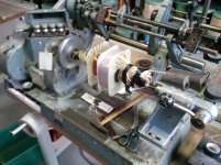
Hi,
yes it is a dedicated winding machine. It belongs to the transformer company as I wrote in an earlier posting.
regards
Wolfgang
yes it is a dedicated winding machine. It belongs to the transformer company as I wrote in an earlier posting.
regards
Wolfgang
Thanks Wolfgang, that would be great if you could find out.
That winding machine looks identical to the one John Chambers and John Wood use, about two thirds of the way down the page: Champ Electronics - Vintage Amp Repairs
Off to the German market in a bit to meet the GF and have a few beers
Cheers
Matt.
That winding machine looks identical to the one John Chambers and John Wood use, about two thirds of the way down the page: Champ Electronics - Vintage Amp Repairs
Off to the German market in a bit to meet the GF and have a few beers
Cheers
Matt.
Hi Matt,
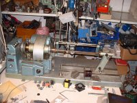
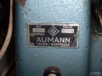
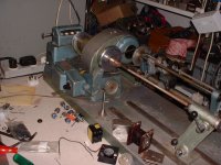
I´d a look at champs side with the winding machine. It is a similar machine, from the same manufacturer "Aumann" . It is a very old german company who made only motor & trafo winding gear.
As I told I used the winding machine by our local trafo company. But since a couple of weeks I came across with an old winding machine.I found it in the farthest corner in a second hand plant & machinery shop. The Manager told me they got this item for several month in stock but no one interested in this piece of iron. Furthermore he sad he will scrap it if there is no customer for it in adequate time. So than I bought it for few Euros. The machine works basically but there are a lot of things to . The machine were stored in a humid warehouse for long time and have now a rust film on many parts.
So I will wound the next transformers on my own winding machine. here pics of my "new" winding machine.
73
Wolfgang
Attachments
Great find! Hopefully it cleans up well, but the most important thing is that you should be able to get it running well.
Keep in mind that the 8 ohm tap on this Output Transformer is actually a 9 Ohm tap<snip>
Once again great job Wolfgang. Quick correction since I had misunderstood my own notes and data. The Plate and cathode loads are at 150 Ohms for all 4 pairs of Push-Pull tubes. The B+ is roughly 470V at idle. However, the 8 ohm tap is really at 9 ohms, so when you apply the 8 ohms load to the 9 Ohm tap you get an effective Plate and cathode load of 133.33 Ohms.
This now extends the plate load high enough to achieve the 500 Watts like the original amps maxed output, the B+ will droop to about 400V at this point.
Wolfgang... if you truly made 8 ohm taps on your secondaries...this would explain why you only reach 450W.
Keep up the great work....I love the photo with the beer..
Chris
Last edited:
Hi Chris,
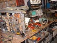
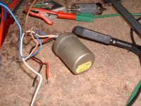
I did some work this weekend on my amp . I made some improvements especially with the wiring. I rerouted the meter wiring from the cathode R´s and the point A&B away from the main harness. Additionally I done the same with the signal input wire. I replaced the wires from the opt to the meter circuit and the meter wires against screened pairs. Away from this I changed the balanced input transformer. I found in my near unlimited bits and bobs two old Sowter audio transformers. I fiddled them in a rough and ready way into the signal path. The did their job excellent.
I did some measurements on a stabilized mains at exactly 230V. The idle input power is 350 Watts, at full blast 950 Watts. The idle current of each output valve is 50mA. The G1 voltage is on all valves between -48 and -53 Volts. The +B is 473 Volts at idle and 440 Volts on full power. The rms output are 450W before clipping. The required input voltage is 0.8V rms.
The amp works stable , but one thing is going to examine. If the amp is turned off, there is a short burst of about 1Mhz for a half a second. Any idea?
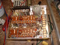
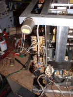
I build the voltage amp section as a plug in module for easier service access. The remained space were McIntosh placed the voltage amp is now for my protection & screen-grid regulator board.
Here are some pics from this weekend:
1. Sowter transformer
2. Makeshift test with the Sowter transformer
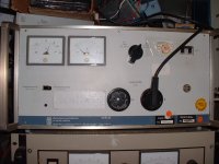
3. Mains stabilizer, Wandel & Goltermann
4. Makeshift test setup
5. Underneath the voltage amp module
6. Voltage amp module
73
Wolfgang
DF6ZC
I did some work this weekend on my amp . I made some improvements especially with the wiring. I rerouted the meter wiring from the cathode R´s and the point A&B away from the main harness. Additionally I done the same with the signal input wire. I replaced the wires from the opt to the meter circuit and the meter wires against screened pairs. Away from this I changed the balanced input transformer. I found in my near unlimited bits and bobs two old Sowter audio transformers. I fiddled them in a rough and ready way into the signal path. The did their job excellent.
I did some measurements on a stabilized mains at exactly 230V. The idle input power is 350 Watts, at full blast 950 Watts. The idle current of each output valve is 50mA. The G1 voltage is on all valves between -48 and -53 Volts. The +B is 473 Volts at idle and 440 Volts on full power. The rms output are 450W before clipping. The required input voltage is 0.8V rms.
The amp works stable , but one thing is going to examine. If the amp is turned off, there is a short burst of about 1Mhz for a half a second. Any idea?
I build the voltage amp section as a plug in module for easier service access. The remained space were McIntosh placed the voltage amp is now for my protection & screen-grid regulator board.
Here are some pics from this weekend:
1. Sowter transformer
2. Makeshift test with the Sowter transformer
3. Mains stabilizer, Wandel & Goltermann
4. Makeshift test setup
5. Underneath the voltage amp module
6. Voltage amp module
73
Wolfgang
DF6ZC
Attachments
MC3500
Dear Wolfgang,
Once again congratulations on a fine job. I have worked on these "beasts" since they were brought to market in 1969. C7 is there to lower the gain of V10 b at high frequencies. I would remove the cathode follower input completely and inject the input signal directly at the R9-R12 junction. No need for the cathode follower. My MI350s have a full constant current driver for the cathodes of the cathode follower and both sections of the ECC83 are paralleled.
If your input sensitivity is 0.8v you have a problem with the gain structure of the amplifier. R22 and R23 at 39K 2 watt need to be much larger wattage types. The dissipation in each resistor is 1.56w and a 2 watt is useless, I use 10 watt resistors in my MI350s. R31 and R32 must be 10K 1% 5 watt types, I had these made for myself. I used only 1% metal film for all resistors in the drive circuit except those 10K 1% 5w types.
The -165v supply should be a well regulated and ripple free supply. I use an electronic regulator with lots of capacitance. The 180v screen supply the same thing. I also use DC on my driver tubes heaters and this lowered my noise floor by over 6dB. I use 72,000mfd in a C-R-C circuit with high speed diodes. The main 470v supply I have added over 1,200mfd of capacitance which improved the transient response my a large margin.
I find no need to match the output tubes as each has its own bias control. Make sure you use the best quality capacitors for the 8mfd and 12mfd capacitors in the bootstrap circuit at the output tranny. Last use tons of capacitance on the +120v, +145v and +395v supplies. Bypass all electrolytics with high quality film types.
Regards
Steve
Zed Audio CA USA
Hi Steve, thanks a lot for all these infos.
As I wrote in an earlier post I like to run the amp first . If everything works properly I´ll make some changes to the odds and ends
The input sensitivy is lower because , I use an 1:1 Input transformer. I need a balanced input, due to use broadcast equipment for my home Audio system and so the lower sensitivy is no issue. Their out put level is +6dBu
The kath. follower is a 6C4 , it has a lower µ. I changed only the kath. R 6 to match this valve to the circuit. The reason to use a 6C4 is, I got them in large quantaties.
The both resistors R31/ 32 in the nfb loop are 5W wirewound Philips/Valvo.
With the regulated -165V I,ll not agree with you. If I use a stabilized Vg1 theres is no compensation angainst mains variation. Unreg. Vg1 means, mains voltage rise, means increasing of +B ; means more idle current. So in this way Vg1 increase also compansate the increasing idle current.
Regulated Vg1 make only sense in a circuit with regulated +B.
By the way the mains voltage here is quite stable , and I got low mains impedance , the power tansformer is in a close range of my home. The Voltage is over the whole day between 230-240V.
The C´s in the power section are all 470µF/450V types. 4 parallel/series on the rectifier, the same as filter C behind the choke and 2 capacitors parallel to +395V and each one for +145 and +120V.
DC heating is a good option to reconsider about it. It is enough space in the amp...
I try with film capacitor across the electrolytics. As you wrote it gives more performance. At the moment they are paralleled makeshift.
once more , thanks for the infos. Its loads of work for the oncoming weeks.
I never saw a MC-3500 in nature , never heard the amp before . I build many amps in my life . I found articles about the MC-3500 in the internet by change , and that was the "wow" effect to me. So my decision was: I will copy this. But to make an amp of this caliber is a real challenge.
73
Wolfgang
DF6ZC
- Home
- Amplifiers
- Tubes / Valves
- McIntosh MC-3500 Schematic Information