It is hard to tell what circuit sounds better. There is a tendency here to do everything discreet and this is an opportunity.
On static distortion the OPA1632 version may be better.
On static distortion the OPA1632 version may be better.
It is hard to tell what circuit sounds better. There is a tendency here to do everything discreet and this is an opportunity.
On static distortion the OPA1632 version may be better.
I fully agree with you.
Why don't we develop both of them and see which one sounds better?
Maybe we could start with the discrete since it is almost done and takes advantage of the Paradise topology which has been succesfully worked for a long time and them move on the OPA's and compare the two of them on the bench and on the listening?
Does it sound good to you?
Yes, i already told you that the balanced Paradise could be for the benefit of others that build it and wish to try this option.
Building the OPA1632 version, why not ?
I am always working on several alternatives.
At the end of the day it is the sound that counts and i have made experiences that have being counter intuitive in the beginning.
Building the OPA1632 version, why not ?
I am always working on several alternatives.
At the end of the day it is the sound that counts and i have made experiences that have being counter intuitive in the beginning.
How would you split it? to in series with two servos one at each end?
Could youy show me the priciple?
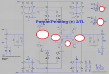
I am aware that I need two servos in the schematic I have included just one but I was playing with the differential one as well.
Most probably ground the emitters of Q65 and Q67, split the resistor on 2 x 100 Ohm (or there about) and ground them. Use the other end's, of the resistors, to connect the servo's. I think 🙂
Most probably ground the emitters of Q65 and Q67, split the resistor on 2 x 100 Ohm (or there about) and ground them. Use the other end's, of the resistors, to connect the servo's. I think 🙂
I had already tried that but unfortunately it seems not to work that way.
If I play around with current source and place one across A- and D- it will correct the differential offset as expected, but I can't come up with something that it would work on that location.
I had already tried that but unfortunately it seems not to work that way.
If I play around with current source and place one across A- and D- it will correct the differential offset as expected, but I can't come up with something that it would work on that location.
Mail me the model, and the components library, then I will have a go.
The problem you have is where to get the control signal (input) for the servo's. This van not be gotten from the output of the RIAA, there the differential errors are already added together and can not be separated anymore. Now that I have given it a second, better, look I do not see where to get the two control signals needed, and how to guaranty (if the input of the servo's does not come from the RIAA output) that the regulated output adds to zero.
The only way to do this is, make the RIAA differential in and out, adjust both sides with servo's, and then add the servo regulated sides into the one output signal. You need a lot more components to do this 🙂
The only way to do this is, make the RIAA differential in and out, adjust both sides with servo's, and then add the servo regulated sides into the one output signal. You need a lot more components to do this 🙂
a lot more
Stick those fancy V-teflons at the inputs, skip the servo's for absolute DC, only add a differential servo for relative DC.
(Servus ?
 )
)
Last edited:
The problem you have is where to get the control signal (input) for the servo's. This van not be gotten from the output of the RIAA, there the differential errors are already added together and can not be separated anymore. Now that I have given it a second, better, look I do not see where to get the two control signals needed, and how to guaranty (if the input of the servo's does not come from the RIAA output) that the regulated output adds to zero.
The only way to do this is, make the RIAA differential in and out, adjust both sides with servo's, and then add the servo regulated sides into the one output signal. You need a lot more components to do this 🙂
And the bonus will be differential output, if you fancy that thing.
The balanced will have an additional problem, once the servo's start to service the servus correction the Dc-out, they will create an input offset and create a current flow in the cartridge. So only a fet version will be possible in a dual symmetric balanced configuration.
An option could be to servo the input and cap the output.
An option could be to servo the input and cap the output.
The balanced will have an additional problem, once the servo's start to service the servus correction the Dc-out, they will create an input offset and create a current flow in the cartridge. So only a fet version will be possible in a dual symmetric balanced configuration.
An option could be to servo the input and cap the output.
Interesting.
Thank you guys for your contribute.
I have the FET version model. However for some reason it seems to be much noisier at low frequency and that is why I was perusing the BJT versions better.
I will post here for the benefit of Frans and the other people here, the model I built with library.
The OPA1632 version is like that. Differential RIAA and differential
servo.
Would you like to carry over in parallel to the topic of the servo, the OPA's approach.
So far I Was unable to get the model up and running.
Sure you are... the unloaded input impedance is 34 M-ohm, but it's used with shunt feedback so the impedance drops significantly and way too low for the casoded fet's to handle.
There's is a way that may work with your interfets, sometime ago I (in this thread) showed an N channel fet RIAA. The top and bottom was mirrored over to a current output node. two such circuits can feed the OPA1632, and you can make 2 servos one from each current output node.
here is the model
Done 🙂
Output Offset 1.3uV
Input Differential 118pV
Servo 1 Output 311uV
Servo 2 Output 550uV
These guys know how to do there stuff, there at the ATL!
Attachments
- Status
- Not open for further replies.
- Home
- Source & Line
- Analogue Source
- Masterpiece