I've put your invert amp in to LTSpice, don't worry I like doing these things.
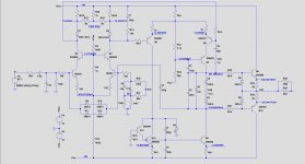
See below the circuit diagram with everything O.K. and all voltages you should see in your amp.
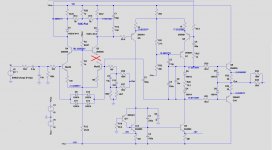
Second image shows what you have with the voltages that you reported.
Most likely is that the collector of your LM394 is interrupted, or the trace to the Q102, the 2N5089 or it's emitter.
Hans
See below the circuit diagram with everything O.K. and all voltages you should see in your amp.
Second image shows what you have with the voltages that you reported.
Most likely is that the collector of your LM394 is interrupted, or the trace to the Q102, the 2N5089 or it's emitter.
Hans
Attachments
great! so I guess I will need to get the board out and check the traces and Q102. When these are ok, then it must be the LM394, right?
is it normal that the inverting input still functions (i.e. I can see the AC signal on 14K7 while playing music)?
One more question, why there is some DC leaking to the LS output at cold? If the 10uF cap is unlikely to be faulty, could it be the 0.022 PP yellow cap that is in parallel with it?
One more question, why there is some DC leaking to the LS output at cold? If the 10uF cap is unlikely to be faulty, could it be the 0.022 PP yellow cap that is in parallel with it?
By the way, I tested and matched Q102 before mounting it, and I check every solder joint with a strong magnifier, so unless Q102 got damaged during soldering, LM394 should be the most likely cause.
great! so I guess I will need to get the board out and check the traces and Q102. When these are ok, then it must be the LM394, right?
Right !
is it normal that the inverting input still functions (i.e. I can see the AC signal on 14K7 while playing music)?
One more question, why there is some DC leaking to the LS output at cold? If the 10uF cap is unlikely to be faulty, could it be the 0.022 PP yellow cap that is in parallel with it?
Yes, a signal will still come out, but distorted.
What exactly do you mean with DC leaking out to the LS output, is it the offset voltage of a few mV that you refer to ?
Anyhow, the 10uF // 22nF are just there to give the amp a gain of 1 at DC, while going to 25 at AC.
So with a gain of 1, the input ofset is only amplified by 1 instead of 25.
Don’t you worry about these caps as long as the LS DC voltage is in the mV range.
Hans
By the way, I tested and matched Q102 before mounting it, and I check every solder joint with a strong magnifier, so unless Q102 got damaged during soldering, LM394 should be the most likely cause.
Transistors normally don’t get damaged during soldering.
However, after having removed the LM394, you still have to check whether the collector is interupted.
Very simple to measure, from base to emitter and from base to collector you should see a diode with your multimeter.
Hans
Yes, a signal will still come out, but distorted.
What exactly do you mean with DC leaking out to the LS output, is it the offset voltage of a few mV that you refer to ?
Anyhow, the 10uF // 22nF are just there to give the amp a gain of 1 at DC, while going to 25 at AC.
So with a gain of 1, the input ofset is only amplified by 1 instead of 25.
Don’t you worry about these caps as long as the LS DC voltage is in the mV range.
Hans
yes what I meant is that the inverting amp is causing a DC offset at cold (ranging from 200mV to 40mV depending on the balancing pot. I will not worry any further then.
Transistors normally don’t get damaged during soldering.
However, after having removed the LM394, you still have to check whether the collector is interupted.
Very simple to measure, from base to emitter and from base to collector you should see a diode with your multimeter.
Hans
ok will do.
Ok I took out the board and both Q102 and the LM394. Strangely they both tested fine with the diode check. The traces are fine. What next?
The old germanium transistors definitely did get damaged during soldering at they were rated for 70C or so, but silicon is way more robust, max junction temps are usually in the 175C or higher range. You'd have to really try to damage it, say by using a brûlée torch rather than an iron!
That’s very strange and frustrating, but the upper board had to be removed anyway.
Are the LM394 diode voltages between left and right absolutely identical ?
I’ll try to molest other parts in the simulation model to get the same anomaly.
You mentioned yesterday that by alternatively shorting the green circles, the other side remained at zero volt, true ?
Hans
Are the LM394 diode voltages between left and right absolutely identical ?
I’ll try to molest other parts in the simulation model to get the same anomaly.
You mentioned yesterday that by alternatively shorting the green circles, the other side remained at zero volt, true ?
Hans
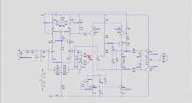
Here's another interruption causing the same problem.
The 100K feedback resistor, or even the 100R resistor going to the base, causing the feedback loop to being broken.
Hans
.
The 100K feedback resistor, or even the 100R resistor going to the base, causing the feedback loop to being broken.
Hans
.
Attachments
Last edited:
Yes, the voltages are similar in the two sides of LM394, although not as close as would have thought. Vbe difference is 5mV between the two sides. The difference in diode voltage between base and collector is 20mV, but I don't think it is important.
Maybe a small circuit can be built to test the LM394 in circuit?
Maybe a small circuit can be built to test the LM394 in circuit?
Here's another interruption causing the same problem.
The 100K feedback resistor, or even the 100R resistor going to the base, causing the feedback loop to being broken.
Hans
.
Let me check this. It could be an issue because in this area there is the add on PCB update implementation where the 470uF cap and 1n4936 diode from the main board get soldered to these resistors thorugh a hole on the upper PCB. Not a neat job and some connection could be defective here.
You mentioned yesterday that by alternatively shorting the green circles, the other side remained at zero volt, true ?
Hans
Yes the voltages were all zero V on that test.
Be aware that a transistor is highly temp sensitive with ca 2mV/degrees.
So this measurement can only be done with hands off after some time of getting a stable temp.
Anyhow, I will do the same measurement.
Hans
So this measurement can only be done with hands off after some time of getting a stable temp.
Anyhow, I will do the same measurement.
Hans
Hans it seems that the 100k resistor is open. I'll pull it out and check precisely. How strange is that though?
I measured one example:
Be aware that between base and emitter there are two opposite diodes, one for protection that is less important.
What I measured:
Left:
Vbe 738mV reverse 910mV
Vce 750mV
Hfe629
Right:
Vbe 737mV reverse 905mV
Vce 751mV
Hfe 630
Hans
Be aware that between base and emitter there are two opposite diodes, one for protection that is less important.
What I measured:
Left:
Vbe 738mV reverse 910mV
Vce 750mV
Hfe629
Right:
Vbe 737mV reverse 905mV
Vce 751mV
Hfe 630
Hans
yes I confirm it's open. Will replace it and everything should work hopefully.
Great you found the cause.
Without simulation model it would have been impossible, wouldn't it ?
Hans
- Home
- Amplifiers
- Solid State
- Mark Levinson protection circuit - Need help