Yes I agree. The circle seems to narrowing down to the front panel circuit.Anyway, by exclusion, other than the amp boards (that are not drawing excessive current), the transformers (that apparently have no excessive losses), and the rear boards (that I also tried disconnecting from the Vcc unreg line), other causes of excessive current draw can only be in the front panel circuit board right? So the relay circuit, or the DC blocking circuit right?
Hans
I started taking so more measurements but not yet finished. Mains voltage over P301-P324 is 219V. I tried replacing the relay with a jumper but that didn’t make much difference (a bit less current but not much).
Then I disconnected the primaries of the right amp and started measuring the left amp. Primary voltages are fine.
I then started measuring currents in and out of the rectifiers for the Vcc unreg and Vcc prereg lines.
For the Vcc unreg lines I calculate an efficiency of the bridge rectifiers of about 67%, whereas for the rectifier of the Vcc prereg lines I calculate an efficiency of 64%. It looks to me like the power loss is coming a bit from every bridge rectifier, at least for the left amp, so maybe replacing all of them would be beneficial?
Also, I just noticed, when measuring current out of the rectifiers I measured DC current (140mA as I posted yesterday), but now by mistake my meter was set to AC current on the -Vcc reg and read 300mA of AC current, does this have any meaning?
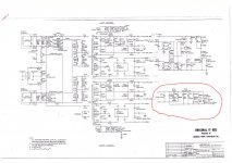
I looked at that, but that's not consuming much power.You also should have a look at the red encircled part of the circuit diagram.
This circuit is consuming power from the 20V windings.
In case one of the components is malfunctioning, it could draw a lot of current.
Hans
Some more precise numbers from the left amp (right transformer disconnected):
only Vcc prereg secondaries connected: 0,282mA from mains (~62W)
0,340mA AC from secondary (*168V =~ 57W)
0,140mA DC from rectifier (*110V = 15,4W , *2 = 30,8W)
So that should be about 50% efficiency, if those 300mA AC I measured on the Vcc prereg line don't matter
With all secondaries of the left transformer connected current draw from the mains is about 650-670mA
I remeasured current from the Vcc prereg lines, this time from the capacitor to the board. Still 140mA DC, no AC current present. So I guess my calculations on the bridge rectifier efficiency should be correct. What you think? Should I try replacing all the 1n4936 diodes in the rectifier and see if it makes a difference?
Another potential cause (maybe more likely?) could be the 0.1uF Wima caps across the secondaries, but I think at this point I should replace all of them, and the diodes, and see what happens.
If any of above components were leaking, they would be above average temperature. Especially compared to similar components on the non-buzzing channel.
However rather than buy an infrared thermometer, I'd dump this piece of **** and buy a blown Crown MA1200 or Peavey PV-8.5c or CS800x . They list on ebay as "amp for parts or repair". At least you would have a 99.99% chance of getting good transformers. If you have 4 ohms speakers you could get 200 w/ch out of a Crown MA600 or a Peavey PV-4C or CS400. If parts amp has blown output transistors or drivers, you could probably salvage the ones out of the buzz dog you own already.
However rather than buy an infrared thermometer, I'd dump this piece of **** and buy a blown Crown MA1200 or Peavey PV-8.5c or CS800x . They list on ebay as "amp for parts or repair". At least you would have a 99.99% chance of getting good transformers. If you have 4 ohms speakers you could get 200 w/ch out of a Crown MA600 or a Peavey PV-4C or CS400. If parts amp has blown output transistors or drivers, you could probably salvage the ones out of the buzz dog you own already.
I appreciate the suggestion, I heard a few professional audio systems, including Crown amps (don't know which model), but to my taste I don't like the sound very much compared to hifi components.If any of above components were leaking, they would be above average temperature. Espceically compared to similar components on the non-buzzing channel.
However rather than buy an infrared thermometer, I'd dump this piece of **** and buy a blown Crown MA1200 or Peavey PV-8.5c or CS800. At least you would have a 99.99% chance of getting good transformers. If you have 4 ohms speakers you could get 200 w/ch out of a Crown MA600 or a Peavey PV-4C or CS400.
I don't see any other components that could be leaking in my amp. The transformers do not have shorts, the people who did the tests are sure of this. I read that transformer efficiency does not get worse with age, but I cannot believe my transformers had a so low efficiency from production, not even cheap chinese products would, so there must be another explanation.
I find HD <.2% to be practically inaudible on speakers. The big difference in amps IMHO is how loud the fan is. I've found QSC fans to be noisy at 1-2 watts (RX85, CX302). The Peavey models I listed the fans are nearly inaudible at low watts. I haven't heard the Crowns, they cost more on ebay than Peaveys. I'm using a Peavey M-2600 in my living room (.15% HD 70 w/ch) with no fan. The one dog I own is a dynaco ST-70 with 1% HD, which sounds a bit fuzzy despite having resale value of ~$1200. I test amps & speakers with piano tracks: very few amp/speaker combos can make a sound like a Steinway 11' grand on all the keys. Top and bottom octaves are particularly tough to reproduce. You can hear real Steinways in person in concert halls & churches to calibrate your ears. Yamaha 11' grand is close but their baby grand models and consoles sound like ****. Great pianos for deaf old men. I can't hear Bosendorfer & Bechstein grands here live, but they sound good on well recorded CD's.
Big difference IMHO is speakers. I spend $50 on my amps, $600 each on my speakers (unless I find a bargain like the year that all the bars the bands played in had to evict customers that smoked).
Big difference IMHO is speakers. I spend $50 on my amps, $600 each on my speakers (unless I find a bargain like the year that all the bars the bands played in had to evict customers that smoked).
Last edited:
I’m outdoors and could not respond. Hopefully I find some time tomorrow.Some more precise numbers from the left amp (right transformer disconnected):
only Vcc prereg secondaries connected: 0,282mA from mains (~62W)
0,340mA AC from secondary (*168V =~ 57W)
0,140mA DC from rectifier (*110V = 15,4W , *2 = 30,8W)
So that should be about 50% efficiency, if those 300mA AC I measured on the Vcc prereg line don't matter
With all secondaries of the left transformer connected current draw from the mains is about 650-670mA
Hans
Ok. Meanwhile I also tested the other channel, disconnecting the primaries from the left transformer.
I have not yet measured all the secondaries, but so far I get the exact same measurements as the left channel:
650mA from mains with all secondaries connected;
330mA flowing through the 168V secondaries of the prereg lines when connected to the rectifier.
I also measured the secondary voltages and are ok, there are no voltage drops when connecting the secondaries compared to the unloaded measurements (actually just 1 V drop for the unreg secondaries, but that was with the amp cold so bias was probably 70-80mV).
I don’t really know how to interpret the results, seems like both channels are working symmetrically, but efficiency is really bad.
Stefano,
Can your multimeter measure inductance with your multimeter?
Then please measure the inductance of the Vcc Unreg winding, so I can do a LTSpice simulation, showing you all the relevant waveforms.
Hans
Can your multimeter measure inductance with your multimeter?
Then please measure the inductance of the Vcc Unreg winding, so I can do a LTSpice simulation, showing you all the relevant waveforms.
Hans
I have two, but I think neither can measure inductance unfortunately, what are you suspecting?Stefano,
Can your multimeter measure inductance with your multimeter?
Then please measure the inductance of the Vcc Unreg winding, so I can do a LTSpice simulation, showing you all the relevant waveforms.
Hans
My idea after doing extensive reading these days is that it might just be a problem of low power factor, where the amp actually draws the correct amount of real power, but there a reactive power, that’s why so much AC current flowing. To make sure I bought a power meter which can also measure power factor. Maybe I will get it later today and can take the measurements.
Yes it’s exactly like this. I hooked up the power meter to the amp, with only one transformer connected, all secondaries and loads connected, bias at 275mA. Power consumed is 92W, about 620mA from the mains (it reads less current than my meter, probably not super accurate). the power factor is something like 0,67, explaining the discrepancy. I did a lot of reading and this power factor seems quite normal for a linear power supply with bridge rectifier and filter capacitors. As far as I understood there is nothing wrong with my amp or transformers. It seems weird however to me that you said you measured ~800mA from mains on other ML23.5 you worked on, which would mean a power factor of 1. I wonder if power factor can depend on the quality of line supply other than the equipment itself.
As far as the noisy transformer, since the noise is proportional to the current in the secondaries it seems that vibrations in the secondaries windings is the most likely cause, either they became loose or because there is too much current flowing. Also wonder if the 1260VA power tranformers can deliver the full output power, given the low power factor.
I still don’t exclude poor quality mains as a cause, especially since the waveform I see on the scope looks quite distorted. If the amp was lighter I would try it in other settings far from the city.
I really measure a power factor of 0.9 (not 1.0) all the time, just like your transformer shop confirmed.
In the end it seems to boil down to your transformers, since everything else is O.K.
So, when you are happy with the sound enjoy it and forget about the hum.
Hans
In the end it seems to boil down to your transformers, since everything else is O.K.
So, when you are happy with the sound enjoy it and forget about the hum.
Hans
Do you mean that the transformers are causing the low power factor? Or just that they are noisy?I really measure a power factor of 0.9 (not 1.0) all the time, just like your transformer shop confirmed.
In the end it seems to boil down to your transformers, since everything else is O.K.
So, when you are happy with the sound enjoy it and forget about the hum.
Hans
Yes I’m happy with the sound and the noise is not at all bothering, as far as the amp is working correctly.
I think I answered the question myself. I connected a purely resistive load to on of the secondaries of the transformer and get a power factor of 0,99 as expected by a transformer. The power factor decreases when connecting the bridge rectifier and filter capacitors. Since the components are all new, and the circuit design should have a higher power factor, as you observed, what could be the problem?
After doing some more tests I see the problem seem to be caused by the big filter capacitors, if I connect a load to the bridge rectifier, excluding the filter capacitors, the transformers are dead quiet and the power factor is 0,9.
I wonder if there is a solution to this, or if it’s just poor quality transformers causing this.
I wonder if there is a solution to this, or if it’s just poor quality transformers causing this.
- Home
- Amplifiers
- Solid State
- Mark Levinson protection circuit - Need help