I can fully understand that you have come to a point where you want to leave it for a while.Hello Hans,
To be honest no I didn’t have the time yet. I was only able to reassemble the transformers yesterday (I replaced the split lock washers that were all flattened out and reinstalling the nut was almost impossible, there wasn’t enough bolt for that… so I had to use a slightly longer bolt, everything’s fine and nothing shorted out ). The transformers still buzz, not sure if a bit less than before. I rechecked all the wiring and all windings are connected correctly with correct polarity, according to the ML23 schematics I have. So I think I will go ahead and measure the current draw of all rails and see if there’s anything unusual.
Facts remain that the transformers should be dead silent and current drawn from mains is too high.
So there must be still something going on that’s not O.K.
Hans
Ok I got the time (and courage) to take some measurements. All Vcc unreg lines draw 290-300mA with bias set to 275mV, so that's good news. The Vcc prereg lines also draw all equal current, about 140mA each, however I measured these between the rectifier and the caps, not between the caps and the boards, I don't know if that makes any difference. If needed I can measure between the caps and the boards but that's more complicated because I would need wires with ring connectors, which I don't have now, or make some other kind of connections on the cap terminals.
So far it looks to me like the amp is working fine and I just got noisy transformers (or very bad DC on the lines that the DC blocker cannot get rid of). The transformer hum definitely varies within the day, but that could also be due to varying mains voltage.
I trust the transformer shop tested carefully the transformers and that they actually work ok.
The secondary currents you have measured are quite O.K., so the "problem" does not seem to be here.Ok I got the time (and courage) to take some measurements. All Vcc unreg lines draw 290-300mA with bias set to 275mV, so that's good news. The Vcc prereg lines also draw all equal current, about 140mA each, however I measured these between the rectifier and the caps, not between the caps and the boards, I don't know if that makes any difference. If needed I can measure between the caps and the boards but that's more complicated because I would need wires with ring connectors, which I don't have now, or make some other kind of connections on the cap terminals.
So far it looks to me like the amp is working fine and I just got noisy transformers (or very bad DC on the lines that the DC blocker cannot get rid of). The transformer hum definitely varies within the day, but that could also be due to varying mains voltage.
I trust the transformer shop tested carefully the transformers and that they actually work ok.
So let's make a calculation:
Vcc prereg is 140mA at 110V. Times two for + and - is 31Watt.
Vcc unreg 300mA at 88V. Times two for + and - gives 53Watt.
Both amps also 2 x (31 + 53) = 168 Watt.
With 90% efficiency this would be 186 Watt from mains or 812mA from mains, fully corresponding to what I usually measure.
However you have measured 1.4 Amp from mains, which is 322 Watt at 230V, so some 136 Watt is vanishing into "something"!.
And because the transformers are humming, the cause seems to be in a possible mismatch between the two transformers.
Suppose one transformer is producing 100-30-30-100 Volt and the second 110-20-20-110 Volt, then because of the two are transformers are in full parallel, they will fight against each other, although each transformer apart is 100% O.K.
That's why I suggested the test in #273 and #274.
Hans
Hi Hans
Actually the Vcc unreg should be around 83,7 V, but that doesn't change significantly the calculations.
I don't have much knowledge about calculating power on the AC line, but are can it be done as for DC (i.e. simply P=Irms*Vrms?). Also, shouldn't we take into account the efficiency of full wave rectification?
I will make the test in #273 and #274, although the transformer shop clearly told me that not only the transformers measured well, with losses only of a few mA, but that they were also closely matched. I also tried connecting only one transformer at a time, and still heard the single transformer hum.
Will let you know about the tests.
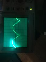
Also, I was looking with the scope at the waveforms on the rectified lines (with and without filter caps connected), and I noticed that the AC waveform is quite distorted (I think from the mains), see the attached picture. I don't know if it is within "normal" real world conditions or if it is enough to make the transformers hum.
Actually the Vcc unreg should be around 83,7 V, but that doesn't change significantly the calculations.
I don't have much knowledge about calculating power on the AC line, but are can it be done as for DC (i.e. simply P=Irms*Vrms?). Also, shouldn't we take into account the efficiency of full wave rectification?
I will make the test in #273 and #274, although the transformer shop clearly told me that not only the transformers measured well, with losses only of a few mA, but that they were also closely matched. I also tried connecting only one transformer at a time, and still heard the single transformer hum.
Will let you know about the tests.
Also, I was looking with the scope at the waveforms on the rectified lines (with and without filter caps connected), and I noticed that the AC waveform is quite distorted (I think from the mains), see the attached picture. I don't know if it is within "normal" real world conditions or if it is enough to make the transformers hum.
Attachments
It is possible, I have not seen these transformers on any pictures online, but there aren't so many with the transformer cover off. That would be very sad, especially after all the work I did on the amp to improve its performance, and still not get the full potential because of poor quality transformers. I don't know anybody who would do a thorough performance test on the amplifier to see if it performs according to specs as far as power and distortion measures.One other cause could be that these transformers are of a much lower grade as ML used to apply, or maybe these are not the original ones
In that case there is no cure and you will have to accept.
Hans
People at the transformer shop however were surprised at how well the transformers measured, that's why the discouraged me to undergo the rebuild, they could guarantee that they would have performed better after the rebuild. Also, they said they didn't hum when they tested them.
So the transformers are well matched and only draw a few mA when idling, that’s how it should be.
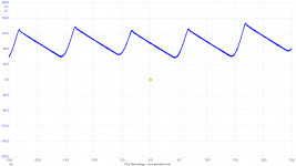
The trace on your scope however looks rather weird, it should show a slow linear decay and a fast recover.
Could you measure the VCC Unreg with your scope on the big cap, it should have a waveform like in the attachment.
With 100Hz, 300mA, 36,000uF and I=C*du/dt, decay should be ca 83mV.
The the 83.7V volt that you mention is on the low side.
So could you measure your mains voltage and the voltage between P301 and P323.
Hans
Attachments
Last edited:
No the picture I attached is without the filter caps connected, so it’s showing the rectified “sine wave”, but looks rather distorted.
With the filter caps connected it looks how it should be.
Mains voltage is 220V. Are you sure 83,7V is low for the Vcc unreg for the ML23.5? That is with the amp boards mounted and the amp at idle.
With the filter caps connected it looks how it should be.
Mains voltage is 220V. Are you sure 83,7V is low for the Vcc unreg for the ML23.5? That is with the amp boards mounted and the amp at idle.
Ok will check that. I can definitely hear the relay kick in however, so I think it is working ok.The reason I asked to measure between P301 and P323 is to check wether the relay is still properly working to shorten the resistors that are limiting the inrush current at seitch on.
One detail about the three current limiting resistors, one of them has the case cracked, but I did check resistance of the three resistors in circuit and they measured ok.
A transformer designed for 60Hz goes into saturation when using it at 50Hz, causing hum and excessive current being drawn.Mains frequency in Italy is 50Hz, how would I know the transformers frequency? There’s no labels. Would like hay cause humming?
Have you any idea in which country your amp was originally sold by ML.
Hans
I have to check, but I think it was imported by sun audio, which should be German if I remember correctly. The marker on the back of the amp is on the 220-240V , but that could have been changedA transformer designed for 60Hz goes into saturation when using it at 50Hz, causing hum and excessive current being drawn.
Have you any idea in which country your amp was originally sold by ML.
Hans
The relay might have burnt contacts, so it could still cause a voltage drop.Ok will check that. I can definitely hear the relay kick in however, so I think it is working ok.
One detail about the three current limiting resistors, one of them has the case cracked, but I did check resistance of the three resistors in circuit and they measured ok.
Hans
P.S. I hope I’m not driving you mad with my questions.
No its interesting to follow the reasoning. If the relay is not working correctly tha could explain why the resistors are cracked, would it explain the humming too? Easy to check I can just use a jumper to bypass the relay and use the variac instead and see if the transformers still hum.The relay might have burnt contacts, so it could still cause a voltage drop.
Hans
P.S. I hope I’m not driving you mad with my questions.
about the transformer frequency, shouldn’t the transformer shop have noticed it if it was a 60Hz transformer?
In theory yes, but maybe they only measured with no load to detect an internal short.about the transformer frequency, shouldn’t the transformer shop have noticed it if it was a 60Hz transformer?
Hans
I spoke again with them, they told me they are 50Hz for sure. They also confirmed the two transformers are identical both for currents and voltages.
But they say they tested them with no load. But they say that 99,9% if the transformers measure fine with no load they have no problems…
They also told me that if the amps consumes 168Watts there should be 700-800mA on the mains, as you calculated.
So next steps are, measure the voltages on p301 and p324 and test the relay. Then try again disconnecting all the primaries from one transformer and see if the other one hums and measure mains current draw.
any chances the bridge rectifiers could be drawing so much,even though I’m sure they test good?
Anyway, by exclusion, other than the amp boards (that are not drawing excessive current), the transformers (that apparently have no excessive losses), and the rear boards (that I also tried disconnecting from the Vcc unreg line), other causes of excessive current draw can only be in the front panel circuit board right? So the relay circuit, or the DC blocking circuit right?
- Home
- Amplifiers
- Solid State
- Mark Levinson protection circuit - Need help