This is exactly the problem I suspected.
With more than 200mV between the resistors, the slow start interferes with the signal. The 500mV is too much.
So the right channel is perfect and the left channel needs some further investigation.
A buzzing transformer normally means that too much current is drawn in idle, are you sure the main voltage straps are in the right position ?
A number of questions:
-Did you replace the two big caps on the upper board
-Which resistors did you replace on the base board and on the upper board. Pictures please.
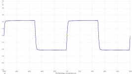
-Can you with your scope have a look at both Vreg voltages in the AC position at start up to see whether oscillations are taking place
Hans
With more than 200mV between the resistors, the slow start interferes with the signal. The 500mV is too much.
So the right channel is perfect and the left channel needs some further investigation.
A buzzing transformer normally means that too much current is drawn in idle, are you sure the main voltage straps are in the right position ?
A number of questions:
-Did you replace the two big caps on the upper board
-Which resistors did you replace on the base board and on the upper board. Pictures please.
-Can you with your scope have a look at both Vreg voltages in the AC position at start up to see whether oscillations are taking place
Hans
This is exactly the problem I suspected.
With more than 200mV between the resistors, the slow start interferes with the signal. The 500mV is too much.
So the right channel is perfect and the left channel needs some further investigation.
A buzzing transformer normally means that too much current is drawn in idle, are you sure the main voltage straps are in the right position ?
A number of questions:
-Did you replace the two big caps on the upper board
-Which resistors did you replace on the base board and on the upper board. Pictures please.
-Can you with your scope have a look at both Vreg voltages in the AC position at start up to see whether oscillations are taking place
Hans
I'll answer your questions in order.
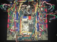
-I'm sure I replaced the voltage straps as they were before, I couldn't know if they were connected correctly to start with, however. But the buzzing was and is simmetrical and dependendent on the bias current (with bias to 0 there's no buzzing and it increases proportionally with buzzing). Only now I notice these intermittent brief interruptions in the buzzing that I don't know where they come from. I'm attaching pictures of how the voltage straps are connected.
-Yes I replaced the big caps on the upper board with the same value capacitors (Panasonic FC).
-I had to replace one of the MJE15030 mounted on the heatsink because I accidentally damaged it during disassembly. It is the one mounted on top, connected to the 2.2R resistor, so the one on the +Vreg section. I'm now starting to think it could be the culprit if it had to be hand selected. I didn't replace any of the output transistor, it turned out that the one that seemed to be acting strangely was fine, it was the meter that was wandering, with the new meter it measured ok.
I also noticed that previously the same transistor on the -Vreg section (MJE15031) had been replaced on this channel. I also replaced the two 2.2R as they looked discolored from the heat and one of them was slightly cracked.
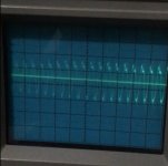
-I checked with the scope and I can see some oscillations for a very brief period of time (fractions of a second) about 3 seconds after switch on. I can see them on both +Vreg and -Vreg on this channel. On the other channel I can also see them but they much much lower amplitude (about ten times smaller I would say). I'm attaching a picture (500mV and .1 microseconds per division).
Are you sure the right channel is completely fine? Earlier I was measuring 40mV on the output after quite some time after switch off when I had the 50k resistors in place (600mV between the resistors for quite some time after switch off too). I now checked however and output went back to normal values relatively soon after switch off.
Attachments
Last edited:
I cant see it on the picture, but for 220V A should be connected to F .
But when V pre reg is ca +/-115 Volt, it is O.K.
Changing the MJE transistors is uncritical, but I'm surprised that the 2.2 R resistors where cracked.
With 50mA, power is I^2*R = 0.005 Watt.
Only at start up they have an inrush in loading the big caps.
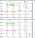
I know the oscillation problem, that's why I replaced those 2.2 resistors with 27R resistors. See image below for better HF suppresion.
But anyhow, does the oscillation completely stop after so many seconds ?
Then I would leave it as it is and see what happens with a load on the LS output, something like 10R or whatever you have.
But I remember thatr you also mentioned to have replaced 2N5401 and 2N5550 transitors by MPS versions.
Where was that ?
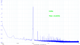
The best final checks are putting a 10Khz square wave at the input with 8R load and to measure distortion at 1Khz.
But might be out of your reach.
Hans
But when V pre reg is ca +/-115 Volt, it is O.K.
Changing the MJE transistors is uncritical, but I'm surprised that the 2.2 R resistors where cracked.
With 50mA, power is I^2*R = 0.005 Watt.
Only at start up they have an inrush in loading the big caps.
I know the oscillation problem, that's why I replaced those 2.2 resistors with 27R resistors. See image below for better HF suppresion.
But anyhow, does the oscillation completely stop after so many seconds ?
Then I would leave it as it is and see what happens with a load on the LS output, something like 10R or whatever you have.
But I remember thatr you also mentioned to have replaced 2N5401 and 2N5550 transitors by MPS versions.
Where was that ?
The best final checks are putting a 10Khz square wave at the input with 8R load and to measure distortion at 1Khz.
But might be out of your reach.
Hans
Attachments
The oscillation only lasts for a fraction of a second, barely visible on the scope, and immediately stops.
Could it be due to degraded 1900uf filter caps?
This channel must have suffered a major failure in the past, and has undergone some horrible repair (most traces attached to the pins connecting the top board had been ripped. Subsequently it has undergone a subsequent repair by a competent professional 10 years ago, who tried to fix as much as possible the previous damages to the top board.
Most transistors on the inverting input section of the top board had been replaced at some point with different ones (2n5401, 2n5551, and some BCxxx). So I have replaced them with the original ones and tried to match them for VBE. I replaced Q101, Q102, Q104, Q105, Q106, Q107, Q108, Q109, Q110, Q111.
As far as measuring distortion, I have a collegue who might have the necessary equipment. Will try to ask him.
I just rechecked V pre reg and it's ±110V. Should I be changing the connections on the PS board?
Unfortunately replacing the 2.2R resistors involves desoldering all the heatsink transistors...not sure I'm ready to go through all that already.
Unfortunately replacing the 2.2R resistors involves desoldering all the heatsink transistors...not sure I'm ready to go through all that already.
Last edited:
No, just leave the 2.2R resistors, they are powering 23.5 amps for ages, but it was simply not the best choice from ML, and when oscillation stops, don’t worry
any further.
A similar thing can be said about the inverting amp, nowadays this whole circuit diagram could be replaced by just one single super performing integrated circuit, which is one of the things I did in my 20.6.
But in your case it’s much better to keep everything in original state.
I wonder what could have happened to this inverting part, thunderstrike ?
Could you adjust offset the way I showed you ?
I’ll send you an instruction how you can simply check the status of the large 4 blue psu caps without having to remove anything.
Hans
P.s. +/- 110Volt is o.k.
I was going to tell you about the offset of the inverting amp, as I tried today to move the trimmer while observing output and voltage between the 50k resistors. If I adjust it clockwise the initial LS output raises from -95mV to -43mV. I can’t get it any closer to 0V with this trimmer. To check the offset I will need to reopen the left side of the chassis to get access to the test point. The voltage between the two 50k resistors still was 500mV regardless of the pot obviously, but there seems to be no relation between it and LS output. Because by the time it got below 100mV the output still was at -40mV.
Is this a sign that the transistors are not well matched and cannot correctly adjust offset with this trimmer? In this case I could try to replace again the transistors after matching more accurately, and maybe match for huge as well?
P.s. thunder strike is a possibility but it’s strange the only section that got damaged was the inverting input section (almost all transistors and a few diodes were replaced.
Last edited:
At this point the amp is functionally as before the restoration, where this channel had an initial offset of 40mV, going to 0.2 mV after warm up. But if the non-matched transistors can have a detrimental impact on the audio signal I would rather replace them with well matched pairs since I have spare parts.
Let me first tell you how to do the cap test for the 4 blue PSU caps.
I=C.du/dt
For the 1900uF caps that are supplying 100mA, this means between two charge cycles:
100mA/1900uF=52V/sec or 0.52V in 10msec.
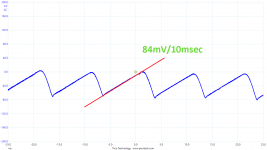
For the 36.000uF caps supplying 300mA, this means
300mA/36.000uF = 8.3V/sec or 83mV in 10msec.
Look at the trace at the image below where I measured the AC waveform with a scope in AC position with a calculated result of 84mV/10msec, very close to the 83mV I just showed.
For the negative supplies the slope is of course inverted.
When your readings deviate quite a bit, put a current meter in the line and check the 100mA and the 300mA.
Hans
.
I=C.du/dt
For the 1900uF caps that are supplying 100mA, this means between two charge cycles:
100mA/1900uF=52V/sec or 0.52V in 10msec.
For the 36.000uF caps supplying 300mA, this means
300mA/36.000uF = 8.3V/sec or 83mV in 10msec.
Look at the trace at the image below where I measured the AC waveform with a scope in AC position with a calculated result of 84mV/10msec, very close to the 83mV I just showed.
For the negative supplies the slope is of course inverted.
When your readings deviate quite a bit, put a current meter in the line and check the 100mA and the 300mA.
Hans
.
Attachments
It is not completely clear what you did.I was going to tell you about the offset of the inverting amp, as I tried today to move the trimmer while observing output and voltage between the 50k resistors. If I adjust it clockwise the initial LS output raises from -95mV to -43mV. I can’t get it any closer to 0V with this trimmer. To check the offset I will need to reopen the left side of the chassis to get access to the test point. The voltage between the two 50k resistors still was 500mV regardless of the pot obviously, but there seems to be no relation between it and LS output. Because by the time it got below 100mV the output still was at -40mV.
Is this a sign that the transistors are not well matched and cannot correctly adjust offset with this trimmer? In this case I could try to replace again the transistors after matching more accurately, and maybe match for huge as well?
The offset of the inverting amp has no effect on the LS output offset because it is AC coupled, it only adjusts the inverting amp itself.
To do this measure the 14K7 resistor between the blue 10uF caps.
One side is going to P1008, but you have to measure the other side while turning the trimmer to get ca 0 volt.
One other thing you could check is to follow back this 14K7 resistor that is connected to a 604//100K.
The other side of these two resistors are connected to twe 20R resistors.
Now measure the voltage over these two 20R resistors, that tells you the bias current of the inverting amp.
In the inverting amp there are two critical transistors, Q100 a LM394 a dual transistor and Q108 and Q109, two 2N5087 transistors that should have been been matched.
I'm surprised that the most critical of them all, Q100 being the input transistor has not been replaced, because this would normally be the first one to die ??
The emitters of Q108 and Q109 are connected to 10R resistors, measure the voltage drop on them and it can be decided whether these transistors can stay or should be replaced.
Hans
I now read your last post, the LM394 seems to be original, I was also surprised that items the only one not to be replaced. I will check the voltage as you suggested.
I understand that it is AC coupled but turning the pot does change the LS output, at least the initial output after switch on. With warm up the output stabilizes anyway at 0.something mV.
Maybe the coupling cap needs replaced? I’m not sure which one it is but I read somewhere that the yellow PP caps should be replaced with X7R ones as they can go bad with age, but I did not replace them. In fact in later versions of the 23.5 I see pictures where they used X7R caps instead of the yellow PP axial caps.
The cap causing the short reaction to turning the pot is a big blue 10uF coupling cap.
They are rock solid.
Hans
They are rock solid.
Hans
I quickly measured the slopes of the 4 big caps on the scope. I see that the 36000uF caps are about 100mV/10msec, so pretty close for both positive and negative on both sides. The 1900uF are difficult to measure safely with the amp assembled so I will take more precise measurements tomorrow. I can see that the ones on the negative side are probably close to 0.75V while those on the positive rail definitely don't look ok. The left side in particular is probably close to 1.5V and has a spike on the leading edge of the cicle. The right channel one looks similar but with smaller amplitude. Tomorrow I will take pictures and more precise measurements, as well as check the current draw.
I repeated all the measurements on the caps. The 36000uF are about 150mV, while the 1900uF are 0.6V for the negative one and 0.75V for the positive one. The big spikes I was seeing yesterday on the 1900uF are not present, not sure what I was measuring yesterday.
I think something is not ok with the inverting circuit however. I checked the voltage on the 14K7 (my bad I forgot to adjust the trimmer when I first reassembled this channel) and its about 15 V after warm up. The trimmer doesn't have any effect on this voltage.
The voltage over the two 20R resistors connected to the 604//100K varies between ca 100 and ca 300 mV depending on how I adjust the trimmer, but it's always asymmetrical between the two resistors.
The voltage over the two 10R emitter resistors of Q108 (I think it'a actually Q106) and Q109 is ca 40mV for Q108 and ca 50mV for Q109. These voltages also vary adjusting the trimmer and the difference between the two is always 10-20 mV.
1) all the ac voltages on your blue caps are twice as high as suspected.
How and where did you measure the 275mA while adjusting ?
2) its obvious that 15V on the 14k7 is dead wrong and the other voltages are rather meaningless because of that.
My first suspect is that the LM394 is defect, but I’ll try to prepare a set of experiments for you to find out.
Hans
How and where did you measure the 275mA while adjusting ?
2) its obvious that 15V on the 14k7 is dead wrong and the other voltages are rather meaningless because of that.
My first suspect is that the LM394 is defect, but I’ll try to prepare a set of experiments for you to find out.
Hans
Is your scope showing reliable voltages ?
You could measure the 220V if possible to get a confirmation.
Hans
You could measure the 220V if possible to get a confirmation.
Hans
Thank you. I think that lm394 is faulty too, it makes no sense that the other transistors got damaged and the lm394 not. Probably it’s not been changed because it’s hard to find but I found a NOS on eBay, hopefully not a fake one. It’s surprising that the amp still sounds good after all with balanced connection.
- Home
- Amplifiers
- Solid State
- Mark Levinson protection circuit - Need help