Excellent 😀 You sound surprised 🙂
Well thats about it then unless you have any questions...
Keep a check on the temperatures of the outputs for a little while but with the bias set to around 10 millivolts there shouldn't be any issues.
Nice work 🙂
Well thats about it then unless you have any questions...
Keep a check on the temperatures of the outputs for a little while but with the bias set to around 10 millivolts there shouldn't be any issues.
Nice work 🙂
well, I guess I was. I was expecting some other issue that you won't find until you connected the speakers and played some thing.
So thank you very much, couldn't have done it without you. it would been down the tip by now, which would have been a shame.
So I think I will run it for a bit and then replace the components on the other channel. Really to keep consistency in part if nothing else
So thank you very much, couldn't have done it without you. it would been down the tip by now, which would have been a shame.
So I think I will run it for a bit and then replace the components on the other channel. Really to keep consistency in part if nothing else
Your very welcome 🙂
If you do the other channel then take it one step at a time following exactly the same test procedure using the bulb.
Its also worth having a good look at the soldering around any of the parts that get hot such as those around Q801 and Q802 and also around D706 and R732 near the chip.
Look at the middle leg of Q352 here. That shows a classic dry joint that could become intermittent.

And same here,

Anything like that could be destructive in a power amp so give it all a once over.
If you do the other channel then take it one step at a time following exactly the same test procedure using the bulb.
Its also worth having a good look at the soldering around any of the parts that get hot such as those around Q801 and Q802 and also around D706 and R732 near the chip.
Look at the middle leg of Q352 here. That shows a classic dry joint that could become intermittent.
And same here,
Anything like that could be destructive in a power amp so give it all a once over.
I think the output stage was OK, but I was literally about to turn the amp off after testing the power supplies, bias etc when there was a small flash from the internal fuse and a smell of burnt out components.
before the that the
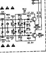
power look good 24v and 17.6v
but the bias on one of the 14mv channels and the other was 10mv
(I stopped at that point as I thought maybe I should turn off and set the bias back to 0, i.e. set the resistor to max resistance. SO I dont know what the dc offset was)
I'm sure I didn't short any thing out, because i was very careful.
Anyway the upshot is that the output on the channel that was dead, is now shot. I took out the mjl21194G on both side and check then, one was Ok the other killed. So I assume that one side survived, but probably need so investigate more.
I don't know how/why the bias had moved at I had the amp running for a 4 days with a test harness to the bias on both side so I could easily check and adjust.
I'm beginning to get a bit discouraged by this turn of events. I spent a while before putting the board back checking for dry joints with a big magnifier light.
And obviously it "worked" for a week and a bit, so I think there must be another issue at play here
before the that the
power look good 24v and 17.6v
but the bias on one of the 14mv channels and the other was 10mv
(I stopped at that point as I thought maybe I should turn off and set the bias back to 0, i.e. set the resistor to max resistance. SO I dont know what the dc offset was)
I'm sure I didn't short any thing out, because i was very careful.
Anyway the upshot is that the output on the channel that was dead, is now shot. I took out the mjl21194G on both side and check then, one was Ok the other killed. So I assume that one side survived, but probably need so investigate more.
I don't know how/why the bias had moved at I had the amp running for a 4 days with a test harness to the bias on both side so I could easily check and adjust.
I'm beginning to get a bit discouraged by this turn of events. I spent a while before putting the board back checking for dry joints with a big magnifier light.
And obviously it "worked" for a week and a bit, so I think there must be another issue at play here
If the DC offset and the bias are (were) correct then that is a really good sign all was OK with the power amp section.
You say both ?? 21194's are short. Or just one channel zapped, with both the 21194 and 21193 short in that one channel.
I take it the amp was running normally cool during all the time its been in use ?
The bias being 10mv in one channel and 14mv in the other is normal, and it will be slightly different each time its measured due to temperature differences on the heatsink. Its always better to play safe and have it at the lower end though because of the finite size of the heatsink.
Could there be any problem with the insulation/mounting of the outputs ?
Only one 21194 was shorted (on the dead channel side), the other was OK (so I put it back in place) - I'll take the 21193 out later and find out.
The amp was running very cool, I put a temp probe on the output when it was running temp, and they were about 24~25c. I could hardly feel the heatsink being warmed.
I actually did an ohms test when I open the case this morning, there were no shorts to the outputs, all reading in M ohm range.
The amp was running very cool, I put a temp probe on the output when it was running temp, and they were about 24~25c. I could hardly feel the heatsink being warmed.
I actually did an ohms test when I open the case this morning, there were no shorts to the outputs, all reading in M ohm range.
If a transistor has gone short circuit then that will show in circuit without having to remove it.
Testing this to get an idea of what has happened involves putting the bulb tester back in place and doing the basic voltage checks.
Which side failed ? Was it the same channel as originally was zapped.
Testing this to get an idea of what has happened involves putting the bulb tester back in place and doing the basic voltage checks.
Which side failed ? Was it the same channel as originally was zapped.
The side that failed was the side that had no sound, which is not the side that was originally zapped.
I checked out the over transistors, only the 21194 and 2n5401 were killed (Q764 and Q756 receptively). I replaced the 2n5401 and removed the 21193, and turned the bias resistor to max (1800ohm) and did a bulb test which was fine. And that where I am at
I checked out the over transistors, only the 21194 and 2n5401 were killed (Q764 and Q756 receptively). I replaced the 2n5401 and removed the 21193, and turned the bias resistor to max (1800ohm) and did a bulb test which was fine. And that where I am at
Last edited:
Hmmm, so its not the original faulty channel. Perhaps in a way that's one positive thing.
OK, lets be realistic... its extremely unlikely that any of the new parts was faulty. So possibilities... if it had been the same channel that failed then there could have been a question mark over some lurking problem, although beyond an odd flaky dry joint, its not something I would have thought likely. However its the other channel that's failed...
Any possibility of an external problem having occurred such as a stray strand of wire shorting at the speaker or amp terminals ?
If you want to carry on with this then obviously the failed parts need replacing. If the 2N5401 failed then I would replace the MJE350 after it as a matter of course.
You need to ensure the output transistors are absolutely perfectly mounted, flat and with not the slightest bit of debris under them so they make perfect contact with the heatsink.
Check all the soldering on the pcb for any tiny (and they can be hard to spot) whiskers of solder between pads around the replaced transistors.
Then its a case of powering up and seeing what the state of play is.
And another thought.
If you have the original transistors then it should be OK to at least get the amp working using those.
If you have the original transistors then it should be OK to at least get the amp working using those.
Well, because of my a carelessness when reordering a replacement output transistor from CPC, I got an "extra" set. I employed those in rebuilding the gone side, so new MJE350, MJL21194, and MJL21193.
So very carefully it rebuilt that side, did some more dry joint checking. Did blub test. checked DC offset on 0.1 got back 14/16.7 mV (Original zapped side - Left and rebuilt side - Right) I assumed the was close to zero but maybe this an issue
Power I got 23.7/17.4. I thought these seemed good, so continued with lamp test with bias, that also looked good. Did the bias for real and checked speaker out got 14.6/16.4 mV. So I thought there only one other test, so added speakers and a input.
And we have sound in both channels! Which is great but also concerning because I was expecting sound from only one speaker. I hate accidentally fixing things (or should I say things working when they shouldn't), I like to know root causes. So it could go again in 2 minute or 2 years.... or maybe never.
The only other thing to add is the repaired side, running slightly hotter that the other. putting a probe on the centre screw I get 29C the repaired side and 27C for the other
That's great that you had the bits to rebuild it OK, its just a puzzle what happened in the first place.
So looking at root causes...
1) Make sure the bias really is OK. Re read post #73.
2 The DC offset is absolutely fine. Problems with that usually show as many volts, typically full supply appearing.
3) Intermittents. Although any component could be intermittent, in practice its very rare to have an odd ball random intermittent failure. Parts that do fail intermittent are usually the ones that run hot (and these are the ones that suffer dries as well).
One area common to both are the regulators. Make sure all the parts are soldered OK. Do either of the two transistors or the diodes look to have been running hot (causing board discolouration or crusty solder). Those would really be the only parts to replace "on spec" as a possible problem but its unlikely they are a problem.
Further testing... with no speakers connected you could heat the amp up with a hairdryer around those parts and just make sure the DC offset remains as it is (any problem with a rail disappearing would affect both channels and cause a massive offset).
If you heat the heatsink then the bias should remain approximately where its set too. It will vary though... the critical thing is that it remains under control such that as the heat is removed the bias always wants to fall back down toward the original setting. Thermal runaway is when the amp heats up, the bias increases, the amp heats more because of this and so on. The bias just goes up and up which is destructive as the output start to fry... from what you say I don't think that is happening here though.
And when measuring remember that even a momentary short is destructive. A short lasting a few micro seconds is all it takes to zap a transistor.
Attachments
1) Make sure the bias really is OK. Re read post #73.
>> I have put test leads on the test point either side of the 0.1 ohm for both channels, and have had a multimeter on while playing and the bias stays roughly at the 10mV level over the 2 hour period yesterday. I kept swapping channel now and then to see if anything had changed.
2 The DC offset is absolutely fine. Problems with that usually show as many volts, typically full supply appearing.
>> OK
3) Intermittents. Although any component could be intermittent, in practice its very rare to have an odd ball random intermittent failure. Parts that do fail intermittent are usually the ones that run hot (and these are the ones that suffer dries as well).
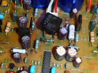
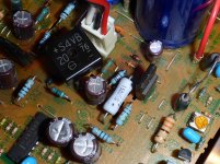
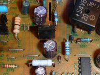
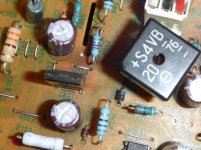
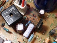
See attached photos, Q801 is to the left of S4VB. The board does look like it's got hot a round both of them. D806 looks a bit "dirty" in on of the photos. One of the photo shows a line coming from D805, it's actually a bit of "glue" from the main caps. Q801 & Q802 running about 45C, I'm surprised they are not on a heat sink.
>> I have put test leads on the test point either side of the 0.1 ohm for both channels, and have had a multimeter on while playing and the bias stays roughly at the 10mV level over the 2 hour period yesterday. I kept swapping channel now and then to see if anything had changed.
2 The DC offset is absolutely fine. Problems with that usually show as many volts, typically full supply appearing.
>> OK
3) Intermittents. Although any component could be intermittent, in practice its very rare to have an odd ball random intermittent failure. Parts that do fail intermittent are usually the ones that run hot (and these are the ones that suffer dries as well).
See attached photos, Q801 is to the left of S4VB. The board does look like it's got hot a round both of them. D806 looks a bit "dirty" in on of the photos. One of the photo shows a line coming from D805, it's actually a bit of "glue" from the main caps. Q801 & Q802 running about 45C, I'm surprised they are not on a heat sink.
Attachments
That all looks fairly typical tbh. The brown paxolin type PCB material does discolour easily with heat. So that in itself is normal.
45C is OK too. It sounds hot but a rule of thumb is that if you can keep a finger pressed on it for at least 5 seconds without burning then its OK. If you look at the data sheets for any silicon transistor you will see typical max junction temperatures of around 150C. I've known transistors under fault conditions get so hot that they unsolder themselves and drop from the PCB, the transistor itself being OK still (although you wouldn't re-use it).
I would just make the comment that those parts that are running hot are the most likely to suffer from soldering problems. Typically you will try and resolder them and find the new solder doesn't "take" cleanly.
The only other possible question mark would be... is either Q801 or Q802 failing intermittent open circuit... which would remove a rail and cause big problems. If that happened both channels would be affected though.
Can you remember for sure whether you heard the interference noise (when it first went faulty this second time) through just one or through both channels. If both then we have to consider the possibility of a common problem such as the regs, if just the one channel then something "unknown" happened.
I think it was in both channels, at first I thought is was part of the music as I was listening to something that I wasn't familiar. but realised it wasn't.
I had reheated both 801 & 802 connections the first time, I think they looked OK. But will check again, maybe clean them up and resolder
I had reheated both 801 & 802 connections the first time, I think they looked OK. But will check again, maybe clean them up and resolder
If the solder takes cleanly to the leads then its fine. Definitely worth going over that area with the iron though, including those resistors. If you think it was both channels affected audibly then that does suggest some common cause, possibly a supply doing something it shouldn't.
Other tests... you could listen at very low volume with the bulb tester in place and with an insulated tool give the board a good prod and poke and see if any noises occur (don't turn it up though as it won't deliver enough current and strange things could happen).
And just check the soldering generally all around the power amp stages including around the IC, but I think you have done that already.
Well, went around the board, cleaned and re-soldered 801 & 802, and generally went around the board.
Did prod test, low volume and with lamp and nothing showed up.
The only thing I can say that was different was the bias, had changed from the 10mv on both channels to 6.3 (new repaired - right) and 7.4 (left), they didn't change after warm up (30 mins). So readjusted them back to 10 mv, and checked this morning and they seem to stay between 9 - 10 mv.
That all sounds good. Don't know what to suggest now...
If there was any possibility something might have shorted or touched the last time it failed, then I would say all you can do is box it up and run it. At the moment everything checks out OK.
If there was zero possibility something happened, then personally I would replace the regulators and zeners on the basis that out of all the components in the amp, these would be the most likely to have an intermittent problem.
I've been coming to the same conclusion that either I shorted something out while testing or it had already happened. that doesn't explain the channel loss
Maybe I should replacement the regulators and zeners. Half the challenge is finding a supplier without paying too much P&P.
Maybe I should replacement the regulators and zeners. Half the challenge is finding a supplier without paying too much P&P.
- Status
- Not open for further replies.
- Home
- Amplifiers
- Solid State
- Marantz PM-66SE KI - bin or repair?