The writing should be on the side that I can't see... is it ?
Are saying that you should be able to see the metal back of Q759?
The left most pin of Q759 is "connected" to the right pin of r773. The left most pin of Q759 should be the emitter, if I understand correctly
And the further checks. Middle leads of all those three transistors on the heatsink do not read short circuit to the chassis... showing the insulating pads are correctly fitted.
Are saying that you should be able to see the metal back of Q759?
The left most pin of Q759 is "connected" to the right pin of r773. The left most pin of Q759 should be the emitter, if I understand correctly
Is it ? Its difficult trying to make it out without a board layout. So the white lines I drew actually go to the left pin of the transistor... if so you have it correct.
nope, the all measure between 99k to 2m ohms
Lets slow down, one thing at a time 🙂
You mean the three transistors on the heatsink read 99 to 2meg. That's correct if so, indicating they are not reading short circuit to the metalwork.
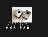
OK, so on the digram the emitter of Q759 goto R773. And your picture of the 340 showed the left pin 3 as the emitter, I assumed the picture showed the frontside (writing side) of the component
so if those two facts are true, the measuring 00.4 ohm between the left pin Q759 and r773 should means that at least that one pin is in the correct place
so if those two facts are true, the measuring 00.4 ohm between the left pin Q759 and r773 should means that at least that one pin is in the correct place
Lets slow down, one thing at a time 🙂
You mean the three transistors on the heatsink read 99 to 2meg. That's correct if so, indicating they are not reading short circuit to the metalwork.
Correct, I'm don't think I implied they were in short circuit 🙂
OK, so on the digram the emitter of Q759 goto R773.
That's correct. Emitter of Q759 to R773
And your picture of the 340 showed the left pin 3 as the emitter, I assumed the picture showed the frontside (writing side) of the component
That's correct too. The picture show the front of the device so you should see the writing
Attachments
Correct, I'm don't think I implied they were in short circuit 🙂
No problem 🙂 we just have to be sure.
Now I'm going to have to disappear in a moment but tomorrows another day🙂
If you are unsure about anything then don't power it up.
The checklist is...
1) All devices in correctly.
2) Bias pot on maximum resistance. In fact, if you are at all unsure on that and which way to turn it then you can fit a wire link across C751 to short the cap out. That applies a short across the emitter and collector of Q751 and forces the output quiescent current to zero.
3) Bulb tester fitted.
I think that covers everything... when you power on the bulb should be dim or out.
The DC voltage on the 0.1 ohm centre lead should be under 100mv or so.
If it passes those tests then its looking good and the next step woul be to set the bias.
(Remember to switch off and pull the plug and wait minute or so for the caps to discharge before touching it with an earthed soldering iron).
OK, some how I missed post #60 with the picture an the red arrow. The red arrow is pointing to the backside. And the side that you can see is the writing side. But the writing doesn't come out on the picture
So I think Q759 and Q757 are in the right places.
Ok, so R755 is turned up to the max, which is about 2200 ohms
So I think Q759 and Q757 are in the right places.
Ok, so R755 is turned up to the max, which is about 2200 ohms
Lets be sure and carry on tomorrow.
If you look at post #46 I drew the transistor symbols showing E,C and B, so you can draw those letters on the schematic if you want and then check the transistor orientation that way. The picture in post #68 shows the exact pin outs.
If you look at post #46 I drew the transistor symbols showing E,C and B, so you can draw those letters on the schematic if you want and then check the transistor orientation that way. The picture in post #68 shows the exact pin outs.
Bulb test work, and the amp didn't burst into flames
Measured from centre of 0.1 ohm, on 300mV scale, got 19 mV replaced side. got 16 mV on the other original side centre. which is under 100mv...
Measured from centre of 0.1 ohm, on 300mV scale, got 19 mV replaced side. got 16 mV on the other original side centre. which is under 100mv...
That all sounds good... very good 🙂
So where are we up too ? What did you do with the bias pot setting for the initial test ?
Assuming all is OK (still the low DC offset) we set the bias next. We do this twice, once with the bulb in place to make sure it all works OK, and then we reset the bias to minimum again, remove the bulb, and set it for real.
Look at the circuit and the 0.1 ohms. Do you see the two "test points" marked at either side of the 0.1 ohms which electrically are the same points as the emitters of the two output transistors. What we have to do is measure the voltage between these two points. Be careful, one slip of the meter and it all goes bang.
Assuming you haven't altered the good channels preset, then I would just do a quick check on that channel and see what the bias is approximately. I would expect around a maximum of around 20 millivolts and probably less. The reading will alter as the amp warms up and will probably seem pretty unstable and varying... that's normal.
The bias setting on the repaired channel can be adjusted to match as a rough and ready check. Assuming it sets OK (and turning the bias up may make the bulb glow) then we set it for real on full mains without the bulb (but turn it back down first).
We could do with finding out what the official bias figure is... but setting it to match the original channel is good enough for now.
More on the bias... no bias will allow audible distortion to be heard at low volume. Increasing the bias even a fraction above zero removes that distortion. The theoretically correct bias for that configuration is probably not sustainable due to the fact that the transistors will generate a lot of heat and being a commercial amp made to a price 😀 there isn't enough metal work and heatsinking to get rid of that heat. That's common in many amps.
So we compromise and set the bias to around say 10 millivolts between those test points (which equates to a current of 50 milliamp... ohms law)
When the amp is all fixed and working its good practice to check the bias again when its all hot and check the bias hasn't increased to much. That third transistor on the heatsink senses temperature and is designed to keep the bias constant with temperature but its an inexact thing so play safe.
OK the last thing I did was bulb test with R755 turned to maximum resistance. And measured voltage centre pin on 0.1 ohm to earth, which was 19mV.
So I read through the your post, but it's not clear what to do next, but heres what I think you said
* measure between test the 2 points either side of the 0.1 resistor array on the underside of board
* determine the voltage of the other channel preset by measuring across R756 as a rough guide for repaired channel
* adjust repaired channel R755 to be like the previous reading - which may the bulb glow (but I assume not brightly)
* the adjust r755 back to max?
* ?? do previous step again but without bulb tester ?? -
Some questions, mostly about meaning of words
Assuming it sets OK- What's OK how can I tell?
but turn it back down first - is that max on R755?
Increasing the bias = a decrease in resistance of R755, or have I got that the wrong way around
How do know the third transistor is working, ie regulating bias. if that failed could that cause the output to burn out??
OK 🙂
What you have done up to now is measure what we call the DC offset. This is the voltage that appears across the speaker terminals and should be near to zero, certainly less than 100mv... and it is. So that's OK.
So the bias and how can you tell its OK.
The bias is the small DC voltage that appears across the 0.1 ohms. What we are actually setting is the current that flows in those resistors, and by using ohms law we can do that easily by measuring voltage instead.
How can you tell its OK.
Turning the preset will cause the voltage across those 0.1 ohms to increase. With the bulb in circuit you will actually see the bulb glow as current is drawn. Seeing the bulb glow a little is enough to prove the bias is increasing and that is confirmed by seeing the voltage across the 0.1 ohms increase.
Turn it back down first. Yes, max resistance of the preset (bulb goes out)
Increasing the bias. Decreasing the resistance of the preset increases the bias. It does this by turning off that middle transistor its connected too.
So here is what you do.
1) Bulb in place and switch on.
2) Measure the voltage across the two 0.1 ohms. So that is the same as measuring from emitter to emitter on the output transistors. Do that on the original channel to get an idea of what its set at factory wise. Then check the repaired channel.
We will work on it being around 10 millivolts...
3) As you turn the bias preset the voltage will rise. 10 millivolts between the emitters means that 50 milliamps is flowing. Ohms law, I =V/R so we have 0.01/0.2 which is 0.05 amps or 50 milliamps.
(With the bulb in place, increasing the bias causes the bulb to glow and in turn means the voltage applied to the amp is lower, so don't turn it too much because the behaviour of the amp might be unpredicatable on to low a voltage. Just prove it works and then turn it back again so that the bulb is out)
4) Remove the bulb and apply full mains. Carefully turn the bias up measuring the voltage across the two 0.1 ohms all the time and set it to 10 millivolts. Let the amp warm up and tweak it back to around 10 millivolts again.
Important. Its easy to turn the bias up and not notice your meter lead isn't making a good contact for measurement, you think nothings happening and you keep turning... things get hot and it goes pop. It can help to solder wires to the test points and trap those in the meter sockets and then you have a permanent connection that lets you watch the meter at all times).
And also. Measuring across the resistors means one lead on one end and one on the other end. The readings aren't referenced to ground in this case. It has to be across the resistors. Either way around for the leads, ignore the - sign on the meter if you see it.
And how do you know that third transistor is working. It will be 😀
OK, done a above. putting wires to the test points made thing much easier. Made it so I could test both channels very easy 🙂
So did the above, the original channel settles about 14~16mv.
I seemed to have to turn the preset what seemed like forever before anything happen, but on visual comparison on the resisters then repaired seems to be near the minimum than the other, but not too much
What's next in the testing process
So did the above, the original channel settles about 14~16mv.
I seemed to have to turn the preset what seemed like forever before anything happen, but on visual comparison on the resisters then repaired seems to be near the minimum than the other, but not too much
What's next in the testing process
Last edited:
I missed your post...
What you do next is turn the repaired channel bias back to zero. Then remove the bulb and power up again. Now slowly turn up the bias on the repaired channel to give around 10 to 16 millivolts so that its similar to the other channel.
After a few minutes tweak it back to around 10mv again (we're playing safe with that for now).
One final check by measuring across the speaker outputs to confirm there is no DC voltage present and you are good to test it out on speakers.
Ok, it been running at 10mv for the last half and hour. But I have some DC voltage on the channel of 0.017v
Thats only 17 mv 🙂 so thats absolutely fine. Historically it was reckoned that below 100mv was acceptable, then as the years passed and designs got better then so the figure came down.
Absolutely no problems with 0.017 volts.
So next step is testing for real with speakers.
Absolutely no problems with 0.017 volts.
So next step is testing for real with speakers.
- Status
- Not open for further replies.
- Home
- Amplifiers
- Solid State
- Marantz PM-66SE KI - bin or repair?