The parts are pretty standard and not very critical as they are just used as "series pass" regulators. Maplin ? The zeners can be made up from standard values if the exact type wasn't available. For example two 12 volt ones in series give 24 volts, a 12 and a 6 would give 18 volts. Maplin list the TIP31C transistor. Thats fine for the NPN one. They have a BD442 that would be OK for the PNP.
The MJE340/350 are as good as any too. Do you have any known good original devices left from the second channel you rebuilt (because we know that channels was OK at the time) ? The driver transistors would be fine to use.
The MJE340/350 are as good as any too. Do you have any known good original devices left from the second channel you rebuilt (because we know that channels was OK at the time) ? The driver transistors would be fine to use.
Sorry, little confused, I thought this was the area that needed matched components? (Maybe I misunderstood a previous post)
So this is what I think the existing component are:
D701-704, 802, 803 - 1SS254
D705 - MTZJ82C
D706 - MTZJ16A
D801 - S4VB-20
D804 - BZX79-C24
D805 - BZX79-C18
D806 - S5688G
Q801- 2SC4883 (Y)
Q802 - 2SA1859 (Y)
so which were you talking about?
So this is what I think the existing component are:
D701-704, 802, 803 - 1SS254
D705 - MTZJ82C
D706 - MTZJ16A
D801 - S4VB-20
D804 - BZX79-C24
D805 - BZX79-C18
D806 - S5688G
Q801- 2SC4883 (Y)
Q802 - 2SA1859 (Y)
so which were you talking about?
It was really just the two transistors, Q801 and 802 and the two zeners, D804 and D805.
Do D705 and D706 look like they have been running hot ? Soldering OK on those ?
Do D705 and D706 look like they have been running hot ? Soldering OK on those ?
D705 and D706 look fine, cleaned them up and resoldered anyway, as I was reoldering some of the links that had minimal solder and looked a bit like future candidates.
The only other place that shows slight browning of the board, is around D702, D704, Q704 and the counter part on the other channel (D703,D705, Q705). but if there was a problem there it would only affect one side.
bias seems be stable, returned from cold to where it was set yesterday
I'll run it today low on the lamp test and see if anything changes...
OK, so it all sounds good at the moment. Any suspect soldering anywhere around the channel that failed would be a prime candidate really, more so than the possibility of an intermittent part really.
So yesterday testing amp on lamp, everything stayed normal, both bias sticking about the 10mV level. But after the about 5 hours, the newly repaired channel move down to 7.5 mV level and stayed there. After 3 hours I adjusted it back to the 10mv level. Which it stayed at until switch off 5 hours later.
This morning, after the warm up (20 minutes) both channel return to previously set values. But I did notice something, which maybe nothing. After cold switch on newly repaired channel rose to 13.5 mv after about 8 minutes and then fell away back to the 10 mv at 15 minute. The other channel rose to 9.9 mv at 8 minute and just stayed there. Which I thought was odd because I thought that should be some moving around as things warm up there would be some movement(?)
This morning, after the warm up (20 minutes) both channel return to previously set values. But I did notice something, which maybe nothing. After cold switch on newly repaired channel rose to 13.5 mv after about 8 minutes and then fell away back to the 10 mv at 15 minute. The other channel rose to 9.9 mv at 8 minute and just stayed there. Which I thought was odd because I thought that should be some moving around as things warm up there would be some movement(?)
That sounds pretty normal tbh.
What happens is this... the gain of any transistor and the voltage needed to turn it on and overcome the nominal 0.6v B-E threshold varies with temperature. So you switch on and set the bias. Within seconds the semiconductor junction within the output transistors is heating and already altering the apparent bias setting. It seems as though its rising. That heat takes some time to spread through to the heatsink. The other channel is doing the same. So the heatsink starts to rise in temperature. That third transistor on the heatsink is mounted there, not because it runs hot, but because it can be used as a thermal compensation device. As that transistor heats, it too conducts more and as a consequence the bias control voltage falls, pulling the bias current back down. For a state of thermal equilibrium to be reached means the amp has to be on for some time so that all 6 transistors on the heatsink are the same temperature.
Its a bit like holding a copper pipe in both hands. Heat one side and it gets hot quickly. The other end takes a little time for the heat reach it. When it does, it can be used to sense and turn the overall heat down. But then there is a see saw effect and it takes a long time for the whole system to reach thermal stability.
So your measurements seem essentially fine. The voltage fell back after 15 minutes because the heatsink would be at a more constant temperature after that time. There would be no harm in just pulling it back slightly though... always always better to have it slightly low rather than too high. Make sure you finalise the adjustment on full mains and after having the top on the amp (so it all gets to normal temperature).
Thanks for the explanation. That tallies with the repaired channel, but does that mean there's something wrong with the other, which just rises and stops without a kind of equalisation seeming to happen. I thought I would see the same type of change in voltage on both channels. (I can't believe that one heat sink is warming significantly quicker than the other)😕
I don't think there is any thing wrong and the way the compensation works is quite sensitive. If you monitor the bias and just blow on the sensing transistor then there is a good chance that alone would be enough to alter it quite noticeably. The thermal capacity of the heatsink will be unequal between sides too, due to the case and components bolted to it (transformer for one ) being none symmetrical.
Its all normal... and you'll never get the two channels to track each other exactly... but what does matter is that the bias always falls back to around the set figure no matter how hot the amp has got. The danger point is when the bias creeps up and up without stabilising. That would happen if that sense transistor wasn't in contact with the heatsink.
Set it, forget it 😀 and enjoy.
 I can't believe it, just put all back together. Turn it on and tick, amp light on an off. Blooming power switch has broken, won't stay in!!!
Just took a part again, yep it's the power switch.

That must be a one in a million fault on a unit like this... wonder if it could have been arcing or doing something strange and that is the cause of all the problems. I wonder how unique it is physically, to replace with an off the shelf item... although the days of such spares being readily available have rapidly declined.
Its easy enough to link the switch out of course to make sure it all works. So I dunno on that one, getting a replacement could be tricky although I haven't looked.
Its easy enough to link the switch out of course to make sure it all works. So I dunno on that one, getting a replacement could be tricky although I haven't looked.
I haven't turned anything Marantz specific up. The switch is likely a Philips part. Ingenuity ? Could something like the years old generic TV on off switch be made to fit. They come in many shapes and sizes but all have the same type of shaft... give or take.
Something like this,
Switch Mains On/Off 2.5Amp
It would need a bit of mechanical ingenuity to secure it.
Something like this,
Switch Mains On/Off 2.5Amp
It would need a bit of mechanical ingenuity to secure it.
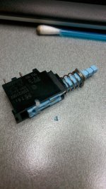
Right style, more like this
http://www.uxcell.com/250v-40a-self-locking-spst-push-button-power-switch-sw3-pcs-p-293761.html
the picture is of it but with the metal casing top removed, so see it the pin and become dislodged. but the was just a bit of loose blue plastic...
body H18mm x D 27 X 10
total length 44mm
I thought this would be easy to find, but so far only something from hong kong on ebay
Attachments
I think you'll be lucky to find an exact fit tbh unless it was ordered as a spares item from Marantz.
I honestly don't know what to suggest at the moment. I think I would probably link it out and prove the amp 100% before going further, and in the meantime see what the possibilities are.
(couldn't open the link 🙂)
I honestly don't know what to suggest at the moment. I think I would probably link it out and prove the amp 100% before going further, and in the meantime see what the possibilities are.
(couldn't open the link 🙂)
Newark in the US (Part of Farnell group) and digi-key and others in the US sell E-Switch products there, like this one:
P197EESB - E-SWITCH P197EESB - SWITCH, PUSHBUTTON, SPST, 10A, 250VAC | Newark element14 US.
Their UK counterparts don't offer this style of switch but all you need is a rule to verify from the PDF that it may fit well enough.
Its not that parts aren't available, but only in certain countries. It may be a safety issue or lack of market interest in the UK, as these types haven't been fitted to new equipment for ages, AFAIK.
thanks, looking at the data sheet that's exactly it.
It's strange these type of switches used to be on loads of things, but I guess the introduction of low powered devices has seen their demise (well in the UK). I suppose when I bought this amp, internet was via modem, mobiles phones were semi-bricks and I could fix my car without a computer
It's strange these type of switches used to be on loads of things, but I guess the introduction of low powered devices has seen their demise (well in the UK). I suppose when I bought this amp, internet was via modem, mobiles phones were semi-bricks and I could fix my car without a computer
BTW I think I've the found reason lost for the loss of channel. The ribbon cable going from the master volume knob board to connector was a bit dodgy, and the case top pushed it in such a way to lose a channel. It was fairly obvious as case off both channels case on one channel.
I think your theory about the switch arcing may have been correct, the internal contact were cover with black carbon deposit, but I couldn't see any pitting. All these type of switch might look like that inside, I'm in the habit of opening them up too often. So place a link in where the switch should be, while I try a reasonable way of sourcing another. I've got to say I can live with it.
I think your theory about the switch arcing may have been correct, the internal contact were cover with black carbon deposit, but I couldn't see any pitting. All these type of switch might look like that inside, I'm in the habit of opening them up too often. So place a link in where the switch should be, while I try a reasonable way of sourcing another. I've got to say I can live with it.
Dodgy switches can certainly be a cause of problems, used to see it a lot in the earlier days of TV repair. The ribbon cable sounds another unusual problem (on a Marantz anyway), great you found the problem though.
the ribbon was Ok, but the connector on the supplementary volume board had a dry joint. which 90% time was ok, but if the ribbon pushed the connector in a certain way then it lost a channel.
- Status
- Not open for further replies.
- Home
- Amplifiers
- Solid State
- Marantz PM-66SE KI - bin or repair?