R802/804 are 47 ohm - actually there was a problem with the amp powering up which was due to the failure R802/804. (I think I may have had the channel problem about the same time, memory not to clear on that)
I just don't think I'm going to get a decent enough reading to be useful. I think just replace instead, it will probably quicker in the long run.
Yes the transistors sit on a white strip, which is "stuck" to the heat sink, you can see it on the picture in post #1. The transistors seem to be bonded on, but maybe this has been caused by time/heat and have in effect seating them in. In fact trying to workout how to remove them without further damage.
R733/R734 = 10.4 both of them
Hmmm... when you say they appear "bonded", have you removed any screws from the transistors or any clamps ? I can see an "outline" on the tops of the transistors that show they had some hardware bolted to them to secure them.
None of that is a problem as long as we know what's needed such as nuts and bolts, insulating kits etc.
None of that is a problem as long as we know what's needed such as nuts and bolts, insulating kits etc.
I removed the brass transistor covers for the picture. I still have all the necessary fittings.
The transistors had become stuck to the insulating "white strip" layer, akin to a piece of white paper, with a little more effort they came loose. but not cleanly leaving some of the strip on the back of the transistors. It not surprising they together for the last 18 years
The transistors had become stuck to the insulating "white strip" layer, akin to a piece of white paper, with a little more effort they came loose. but not cleanly leaving some of the strip on the back of the transistors. It not surprising they together for the last 18 years
Are we assuming that all the transistor will be shot?
(Should I replace the same of the other channel?)
2SC3182 Semiconductor General Transistor (TO-3P) - Q761
2SA1265 Semiconductor General Transistor (TO-3P) - Q763
2SC2240 Semiconductor General Transistor (TO-92). - Q753
2SA970 Semiconductor General Transistor (TO-92) - Q755
2SB1353 Semiconductor Marantz Transistor (TO-126) - Q759
2SD2033A Semiconductor Marantz Transistor - Q757
74PM66/95B Resistor 0.1Ohm 3W Marantz or 0.1R 5watt Resistor Axial Wire/Wound (25x6.4mm)
plus.. insulator kit
plus...
I would be looking to replace outputs, drivers and pre drivers. That's six devices per channel. Do you replace the same on the other channel... if it were me then yes, I would.
Parts... ebay as a source of semiconductors is not recommended... way to many fake devices around.
What I would suggest (and what I would do if given one of these as faulty) is fitting devices such as 2N5551/2N5401 for Q753 and Q755, possibly MJE340 and MJE350 for Q757 and Q759 and possibly MJL21193 and MJL21194 for the outputs. All available from suppliers like CPC.
CPC | CPC - Over 100, 000 products from one of the worlds leading distributors of electronic and related products.
so this may be a stupid question, what's the advantage behind using alternative parts? is it better products (more detailed sound), cost, ease of supply.
It seems that replacement for the existing item can be sourced, so why not use them?
What should I be look for for insulation?
It seems that replacement for the existing item can be sourced, so why not use them?
What should I be look for for insulation?
Using higher spec components can sometimes lead to problems. If you unaware of what to do if things go wrong I would stay with the correct replacement parts.
Insulation - surely you took the thing apart, you can see what was used originally.
It is fairly common for manufacturers to use "Insulated Tab" transistors that don't require any insulation, just thermal paste. Check to see if you have any metal exposed on the rear of the transistors.
Insulation - surely you took the thing apart, you can see what was used originally.
It is fairly common for manufacturers to use "Insulated Tab" transistors that don't require any insulation, just thermal paste. Check to see if you have any metal exposed on the rear of the transistors.
Last edited:
KatieandDad,
Yes, I can see what it is, but what's it called. it's flat paper like insulating strip, googled but can I find anything like it, No. So I'm obviously missing the right term.")
Both the original and suggested parts have bare metal backs.
So these are high spec parts and not just alternatives??
The obvious different is the +£30 for the original parts list compared to the ones Mooly suggested
Yes, I can see what it is, but what's it called. it's flat paper like insulating strip, googled but can I find anything like it, No. So I'm obviously missing the right term.
Both the original and suggested parts have bare metal backs.
So these are high spec parts and not just alternatives??
The obvious different is the +£30 for the original parts list compared to the ones Mooly suggested
so this may be a stupid question, what's the advantage behind using alternative parts? is it better products (more detailed sound), cost, ease of supply.
It seems that replacement for the existing item can be sourced, so why not use them?
What should I be look for for insulation?
Its a good question... and the main one is ease and speed of supply and knowing the provenance of the parts is good i.e. they are what they say they are.
Don't let what I say stop you getting original parts if that's what you want to do
Although semiconductor properties can have an influence on how a circuit behaves, for an amplifier like this there should be no problem using alternative devices... and alternative devices don't mean poorer "pattern parts" like you might associate with say domestic appliance or car spares... these are "proper" (if that's the word) devices in their own right.
There will be no difference in sound quality using different devices.
Insulating kits are no problem... once you've decided what devices you are going to use, then the correct kits can be obtained.
Thanks Mooly,
I'm balancing up - COST vs my lack of expertise (vs to lesser extent sound)
Currently it will cost me nothing to do nothing and keep non-working amp non-working. or I can try to repair it, which may or may not work, either spending £25~ or £60~. I'm the main risk factor in the equation, so how lucky do I feel, probably less than £50 lucky.
I agree the value of knowing where the parts come from, and steer well clear of ebay (and alike) for electronic components. I'm always dread what I'm going to find when a friend or family member asks me to have a look at something thats broken that they bought cheap of ebay.
Farnell/element14 have all the items suggested. I've not used CPC before, and using farnell will save me registering with a another components company, it will only be another password to forget.
BTW I found most of the original parts at Charles Hyde & Sons, I've not use them before either, but I assume they're kosher
Q751 should be OK, Q801 is a "series regulator" and could run quite hot. Board discolouration is normal in lots of situations, it doesn't indicate a problem.
Now, to have any chance of success with all this (and there is a very good chance) involves far more than just replacing parts and hoping for the best. At every step of the way it involves checking and testing as the amp is built up (nothing complicated, just very simple voltage checks along the way). But it must be done methodically
That process can start without replacing anything if you want, and would involve reassembling the amp, removing the obviously failed devices, and then powering up with a bulb tester to see what the state of play is, and in so doing making sure there are no other obvious problems. In fact that might not be a bad idea actually.
CHS are fine and are a well established trade supplier although its quite a few years since I have dealt with them on a regular basis. CPC (part of Farnell) are generally pretty good I find and I deal with them all time. Farnell are excellent but more pricey and have delivery charges.
when you say the obviously failed devices, do you the physically damaged component only?
Will I need speakers attached?
Will it be ok to use the existing transistor insulation, as part of the white coating has come off, what I guess is a mica strip?
What wattage bulb would be best?
And what am I expecting to see? (I assume half bright bulb)
Will I need speakers attached?
Will it be ok to use the existing transistor insulation, as part of the white coating has come off, what I guess is a mica strip?
What wattage bulb would be best?
And what am I expecting to see? (I assume half bright bulb)
Here's how it goes...
1) The amp is all put back together but there is no point having the two obviously zapped output transistors fitted. So either unsolder and remove them or snip them out.
2) The driver transistors are removed. That is Q757 and Q759.
(Solder braid is excellent for removing components cleanly and without causing damage to the PCB)
3) The "good" channel has its output transistors all secured back in place. Don't over tighten them at this stage as they might be being swapped again anyway.
4) At this point a basic resistance check is performed to make sure those transistors are insulated from the chassis. That means reading from the middle lead of each device to the metal work of the amp. As long as there is not a dead short then its OK. (And this is the kind of problem that the bulb tester picks up without any damage occurring)
The bulb tester... is a filament type household bulb. Normally a 60 or 100 watt is ideal. You can wire this either external to the amp or (what I normally do) solder a couple of wires to the bulb and wire it across the internal mains fuse having removed the fuse first. Safety is important so make sure no hands can grab the bulb etc.
And at NO point are speakers or anything else attached to the amp.
When you switch on the bulb should give a bright flash and then essentially go out. If that happens then it means that there is no excessive current being drawn anywhere. If the bulb stays lit then there is a problem that can be investigated safely.
Assuming the bulb is out or very dim then those regulated voltages (Q801/2) can be checked. But be careful... one slip of the meter lead could cause more damage so lets take it one step at a time.
Attachments
Ok, so removed Q673/671 Q757/759
I already had a built bulb tester for something else, where the appliance plugs into the bulb tester, so it's before the internal fuse. But in essence it's doing the same job.
So flash of light and then bulb not lit ( not that I could see), after 3 seconds the clink sound you get with this amp.
Measured +24v and -18v from Q801 and Q802 respectively, 22.7 & -16.8. Not sure if that's good new of not
Q751 should be OK, Q801 is a "series regulator" and could run quite hot. Board discolouration is normal in lots of situations, it doesn't indicate a problem.
Now, to have any chance of success with all this (and there is a very good chance) involves far more than just replacing parts and hoping for the best. At every step of the way it involves checking and testing as the amp is built up (nothing complicated, just very simple voltage checks along the way). But it must be done methodically
That process can start without replacing anything if you want, and would involve reassembling the amp, removing the obviously failed devices, and then powering up with a bulb tester to see what the state of play is, and in so doing making sure there are no other obvious problems. In fact that might not be a bad idea actually.
CHS are fine and are a well established trade supplier although its quite a few years since I have dealt with them on a regular basis. CPC (part of Farnell) are generally pretty good I find and I deal with them all time. Farnell are excellent but more pricey and have delivery charges.
I've used Cricklewood Electronics for many years with no problems and their prices are very good.
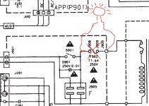
That all sounds good so far. The voltages on the diagram are open to interpretation, for example the +24 volt rail will be the actual voltage across zener diode D804 less the 0.6 volt drop of D802 and less the 0.6 volt drop of the base-emitter junction of Q801. Same theory for the -18 volt rail too... so yes, all is well there.
The relay clicking suggests there is no DC offset present on the good channel. You can measure it if you want. There should be essentially zero volts DC on the centre lead of the 0.1 ohm resistor network in the good channel.
So up to now all good. All you need are the replacement bits... if you want me to come up with some part numbers from say CPC or Farnell then I can do. Up to you
- Status
- This old topic is closed. If you want to reopen this topic, contact a moderator using the "Report Post" button.
- Home
- Amplifiers
- Solid State
- Marantz PM-66SE KI - bin or repair?