CPC seem to do most of the stuff although they don't list the 2N5401 transistors I mentioned. We can use MPSA92/42 though. I've put 3 and 5 down for quantities because they are useful general purpose devices and at the price worth getting... you never know 🙂
Is there anything I have missed ? If you order from CPC double check the items as you enter them in just to be sure and to make sure the order multiples are correct.
2 off MJL21194G, order code SC06819 at £3.47 each.
2 off MJL21193G, order code SC06829 at £3.47 each.
3 off MJE340, order code SC06487 at £0.47 each.
3 off MJE350, order code SC08528 at £0.23 each.
1 off MPSA92, order code SCMPSA92 at £0.828 (priced per pack of 5)
5 off MPSA42, order code SC06677 at £0.084 each.
4 off 0.1 ohm/3watt, order code RE04654 at £0.54 each.
1 pack 2.2 ohm/0.25w, order code RE03778 at £0.59 each.
5 Kapton insulators, order code SC10731 at £1.08 (outrageous price but they are good... minimum order quantity 5)
Do you have local Maplin ? If so you could get a couple of 2N5401 transistors which CPC don't stock. Maplin code: UL37S at £0.49 each and then ADD five 2N5551 transistors to the CPC list. CPC code SC06652 at £0.09 each. These would be an alternative for the MPSA devices and always useful to have.
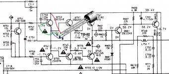
I think I want to R763/R764 330ohms, one obviously got a bit hot by it colour. On the diagram it says 1w but the board has 2w version, I assume the 2w RE04262 or RE05185 (1w RE04327)
OK, the 1 watt ones are fine. I suspect its specced as a 1 or 2 watt device to enable a "safety component" to be fitted. These are typically metal oxide and if a fault occurs and the resistor gets to much voltage then it fails without smoking 😀
The 2 watt ones are not in stock, the 1 watt are pricey when you only need a couple. I'd be very happy fitting something like these,
MCF 1W 330R - -- - RESISTOR, 1W 5% 330R | CPC
In normal use that resistor never sees more than a couple of volts across it and so a 1 watt is fine. The absolute voltage varies in sympathy with the audio and so can reach as high as -/+35 volts or so at full output but the differential across the resistor is always very low.
ok, ordered part on Monday, and arrived today!
And also managed to pop-in to Maplins on my journeys as well.
So I'm in a position to be able to replace the parts
And also managed to pop-in to Maplins on my journeys as well.
So I'm in a position to be able to replace the parts
Excellent.
I remember we tested the amp with the bulb tester and all seemed good (apart from the zapped channel) so I would suggest re-building just the zapped channel to begin with.
I would start by removing the parts to be replaced, so that's the six transistors, the 2.2 ohms, the 330 ohm and the 0.1 ohms. Replace those with the new parts. For the 0.1 ohms you will have to see how they fit and look. I would perhaps fit them vertically with one resistor using centre and outer hole and the other using just the outer hole with its other lead soldered as shown here.
The transistors we fit one at a time beginning with Q755 and Q753.
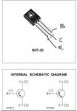
Familiarise yourself with the pinouts by using this link. Just type the device number into the blank box.
Datasheet catalog for integrated circuits, diodes, triacs, and other semiconductors, view
I'll be back later... don't rush it and don't attempt to power it up. There is more to do and it all has to be checked.
What devices did you get in the end... MPSA92/42 or 2N5551/2N5401 ?
I remember we tested the amp with the bulb tester and all seemed good (apart from the zapped channel) so I would suggest re-building just the zapped channel to begin with.
I would start by removing the parts to be replaced, so that's the six transistors, the 2.2 ohms, the 330 ohm and the 0.1 ohms. Replace those with the new parts. For the 0.1 ohms you will have to see how they fit and look. I would perhaps fit them vertically with one resistor using centre and outer hole and the other using just the outer hole with its other lead soldered as shown here.
The transistors we fit one at a time beginning with Q755 and Q753.
Familiarise yourself with the pinouts by using this link. Just type the device number into the blank box.
Datasheet catalog for integrated circuits, diodes, triacs, and other semiconductors, view
I'll be back later... don't rush it and don't attempt to power it up. There is more to do and it all has to be checked.
What devices did you get in the end... MPSA92/42 or 2N5551/2N5401 ?
Attachments
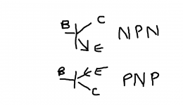
Q753 (originally 2SC2240) will be replaced with either a 2N5551 or an MPSA42. If you have the choice use the 2N devices. Notice how the arrow points outward. That means it is an NPN device.
The pinouts are the same for the MPSA and 2N devices but these are different to the originals. So you will have to neatly bend the leads so they fit correctly.
Q755 is replaced in the same way using either the 2N5401 or MPSA92.
The pinouts are the same for the MPSA and 2N devices but these are different to the originals. So you will have to neatly bend the leads so they fit correctly.
Q755 is replaced in the same way using either the 2N5401 or MPSA92.
Attachments

OK, I've done the resistors and put in Q753 Q755. but I just want to check I've place them right.
Originals = ECB
replacement = CBE
(when viewed from the roundside)
So if I insert the replacement 180 degree, with the base and collect pins swapped, then I should be good
Originals = ECB
replacement = CBE
(when viewed from the roundside)
So if I insert the replacement 180 degree, with the base and collect pins swapped, then I should be good
That sounds OK but describing things is always difficult. I would measure and be sure. Use your meter on its lowest ohms range and confirm for Q753 that the base (middle leg of transistor) connects directly to one end of R757. Now look at the diagram in post #47 for transistor. Confirm that the lead marked C for collector connects directly to the positive rail and confirm that the emitter connects directly to R761.
Then double check that the device is correct, either the 2N5551 or the MPSA42.
Then repeat the process for Q755 confirming the middle leg of the transistor goes to R759 and that the collector goes to the negative rail. The emitter should go to the other end of R761. Now double check the device is the correct one, 2N5401 or MPSA92.
The next pair are easier because the base is at one end and not in the middle. Look at the diagram in post #47. This is looking down on the device (so you should see the markings).
The MJE340 replaces Q757. Makes sure the base connects directly to R761 and that the emitter goes to the 330 ohm and 2.2 ohm.
The MJE350 replaces Q759. As before, check the base goes to the other end of R761 and the emitter to the 330 and 2.2 ohms.
Keep referring to the circuit and checking and it will make more sense.
I've put in Q753, Q755 , Q757, Q759 on the board last night, but is it was late so I didn't snip the legs as I wanted to check this morning when I was wake.
Q757/9 seemed simple, it was Q753/5 I thought I may have got wrong. But I'll check these at lunchtime.
Having a look at Q761/3 replacements data sheet and the original they looked like the same configuration. Although CPC datasheet is an incomplete older version missing the CBE info. The only difficulty here is the physical size of the component, it's gonna be tight fit but it look like it will all fit.
Yes double check everything. The outputs are the same configuration as the originals with the MJL21194 being the replacement for the 2SC device and the MJL21193 replacing the 2SA device. Don't overtighten them when fitting and its also good practice to secure them first and then solder them in so that the leads don't undergo and stress.
When the outputs are secured check that there is no continuity between the centre lead of each and chassis. Due to other circuit components you will see some reading but it mustn't be a dead short indicating that the device isn't insulated correctly.
When the outputs are secured check that there is no continuity between the centre lead of each and chassis. Due to other circuit components you will see some reading but it mustn't be a dead short indicating that the device isn't insulated correctly.
My feelings were right that I hadn't got Q753/5 right, both from your instructions and I also multimeter test on the removed original transistors. (neither of which had failed). I realized I got the wrong side from the datasheet line drawing.
So I re-did those and put on the outputs, and then ran out of time. so I've not done the conductivity on the output yet, will have to wait to this evening
So I re-did those and put on the outputs, and then ran out of time. so I've not done the conductivity on the output yet, will have to wait to this evening
You have to be absolutely sure on these. If you want to post a picture of them then that might help with checking.
The outputs should be straightforward... but whatever you do don't attempt to power it up yet.
The outputs should be straightforward... but whatever you do don't attempt to power it up yet.
I'm pretty sure, if I ignore the original components datasheet and do it by empirical tests, using multimeters test and the circuit diagram it all looks good.
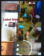
I'm looking at the picture. Q759 which should be an MJE350... I can't see the writing on the device which would identify whether its the right way round.
The writing should be on the side that I can't see... is it ?
The writing should be on the side that I can't see... is it ?
so what's next before powering up?
Whats next. We make absolutely 100% sure all the devices are correctly fitted 🙂
Before you do power it up (with the bulb tester and no speakers) we set the bias preset R755 to maximum resistance. That will give the lowest quiescent current in the output stage.
If you are not sure which way to turn it then measure the resistance between base and emitter of Q751 and turn the preset to the end that gives the highest resistance reading.
- Status
- Not open for further replies.
- Home
- Amplifiers
- Solid State
- Marantz PM-66SE KI - bin or repair?