before anyone tells me I have just realised those voltages are no good for the flea, therefore I now have a use for the 17.7v
So I've fitted an external 2x9V Tx to the rear of the chassis now and used it to feed the servo and the Dac analogue on my CD67. I added a small AC-DC pcb where the fuses used to be and injected the new pre-reg DC voltage in to U264. This means that the 9.3V secondary of my KI Tx now only feeds Q811 (which in turn is feeding DAC digital and the decoder) and an added 7805 feeding the U-com and display (via U156...I think).
I have one more very small 2 x 9V to add for the decoder analogue and digital, then I was going to add another regulator for the HF amp (still fed via the Ki Tx). This should leave Q811 to feed only the DAC digital.
I have one more very small 2 x 9V to add for the decoder analogue and digital, then I was going to add another regulator for the HF amp (still fed via the Ki Tx). This should leave Q811 to feed only the DAC digital.
Sure I'll post some of my current status tomorrow maybe. I have some way to go yet since I have a pair of audio transformers to go in too, to replace the whole analogue stage. Working on the unit is going to get very tricky, very quickly...!
I've never tried a DOS no. I don't really believe in discrete stuff over opamps ever since I read some articles by NwAvGuy.NwAvGuy: Op Amps: Myths & Facts
I'm currently using two LM4562A with the Pensax filter tweak.
I'm currently using two LM4562A with the Pensax filter tweak.
I've never tried a DOS no. I don't really believe in discrete stuff over opamps ever since I read ...
You should try it sometimes ;-) .
I ended up with DOS (Ray adjusted its schematics for me also for attenuated output level to match my tube amp that does not like 2V levels) after listening to about half a dozen different opamps.
I'm currently using two LM4562A with the Pensax filter tweak.
The last opamp that I used was LME49720HA (didn't like 4562 but probably it is a matter of personal taste).
About the output via audio transformers - does your amplifier have balanced or unbalanced inputs?
I too have a valve amp. A modded WAD Kel84. It has unbalanced inputs; just simple phono.
My understanding is that the lme49720 and lm4562 are the same chip. They ought to sound the same. The HA version is the metal can TO99 package though, which apparently sounds slightly better...though no one knows why. Not even the engineers at National apparently.
My understanding is that the lme49720 and lm4562 are the same chip. They ought to sound the same. The HA version is the metal can TO99 package though, which apparently sounds slightly better...though no one knows why. Not even the engineers at National apparently.
I too have a valve amp. A modded WAD Kel84. It has unbalanced inputs; just simple phono.
How long is the signal cable from player to amplifier?
My understanding is that the lme49720 and lm4562 are the same chip. They ought to sound the same.
They don't ... 😉
What audio transformers will you be using?
My leads are less than 1m. Balanced cables only come in to play over 5m I think?
The transformers are silver wound audio consulting from Audio com a few years back. They were Marks last pair.
The transformers are silver wound audio consulting from Audio com a few years back. They were Marks last pair.
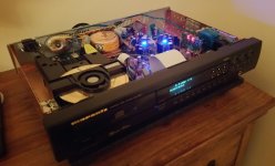
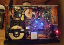
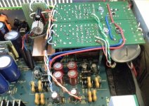
Here's some pics from today. Added my small 2x9V and hooked up one of the secondaries to a dedicated decoder PSU just behind the display panel. I'll be adding a second here to further divide the decoder in analogue and digital.
Attachments
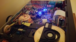
OK, some pics of the DOS and "DOS-corner" of my player (the board on the picture is without transistors).
The opamp buffer to drive a 6m cable is on the left.
On the middle picture the attenuator for adjusting R14 value (between 10R and 50R) is visible.
The opamp buffer to drive a 6m cable is on the left.
On the middle picture the attenuator for adjusting R14 value (between 10R and 50R) is visible.
Attachments

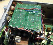
Those caps seem a little over-sized? 450VDC...how much offset you do you have?? 😛
Most probably less than 15V 😉
These are the Mundorf MCap EVO Oil ones (decide to try out the "audiophilic feeling" ;-) ) - I don't think they come in much less voltage in this capacity range...
And they look nice ...
Nichicon Muse bipolar electrolytics are remarkably smaller.
I didn't think the DOS would need coupling caps? I thought all the components were precision matched etc so there'd be no DC offset? I don't use any coming from my inferior opamps ;-)
Nope, DOS needs the coupling caps - as far as I understand the output stage is not symmetrical.
My opamps (also the cable buffer on the photo) "pump" also without output caps, just a 47R resistor on their way.
The output offset has typically been less than 20 mV.
My opamps (also the cable buffer on the photo) "pump" also without output caps, just a 47R resistor on their way.
The output offset has typically been less than 20 mV.
I've separated analogue and digital on the decoder now and I'm liking the results. The decoder chip can be further divided however - is it worth adding lots of extra regs round there? I still need to separate the HF chip supply on the servo board.
Tweaking the DOS
Recently I performed some changes on my DOS. I purchased a set of the LSK170 Jfets from the DIYAudio Store and replaced all the 2sk170's in my DOS. I did this in 2 phases, first go with just the jfets in the differential, and then later with the buffer and current sink jfets.
Upon installing the LSK's in the differential I measured the voltages thoughout the DOS taking careful note of the voltages in the differential. The voltages at the jfet source should ideally be as close as possible. With the miss mash of jfets I originally installed in the DOS there was a fair variance in the source voltages. After installing the LSK's the voltages got very close, though not exactly the same.
In music listening after this installation I picked up a much tighter channel balance and music image than before. This happened fairly straight away. And after a couple days I noticed that there seemed to be a bit more music detail, which I figured came from the low noise aspect of the LSK's and lowering the noise floor a bit.
It was then that I decided to install the LSK's in the buffer and current sink, mostly because I had them. The LSK's are sold in sets of 8, so you have enough to do all the jfets.
I later swapped out the initially installed resistors in the differential for some 0.1% resistors that measured exactly the same for each pair. The voltages moved very little, if at all. Same for sound. But then again, in this circuit it pays to have each pair of resistors exactly the same at initial installation as just a way of doing things. And you have to measure the resistor to know, rather than just read the writing on the label or note the color bands.
I purchased the Grade B LSK's for this. They are somewhat of a no brainer purchase for this as they are only $3 more than Grade C's. They are such a no brainer that they are gone now until next resupply.
I have recently purchased a set of the Grade A LSK's for my other DOS, and in time will get them installed along with everything else I did in the first DOS.
I highly recommend installing the LSK's. But first measure the voltages in the differential circuit. If there is more than a few hundredth's variance, then at least matched jfets should improve this. LSK's, while not perfectly matched, are in pretty close parameters and work well in this application for sure.
With the miss mash of jfets I originally installed in the DOS...
So can the improvement in sound be attributed to LSKs being better (by their characteristics) than 2SKs or to the possibility that you installed a better matched set?
So can the improvement in sound be attributed to LSKs being better (by their characteristics) than 2SKs or to the possibility that you installed a better matched set?
Both
- Home
- Source & Line
- Digital Source
- Marantz CD63 & CD67 mods list