RCruz The project is still ongoing, it ground to a halt over 12 months ago, I have had just too many other things to do, hope to get things going again soon.
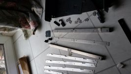
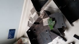
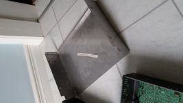
Firstly I had to figure out how to use the software for creating DXF files for laser cutting, the main chassis was cut and folded by someone in Ireland. Most of the rest of the pieces I had cut by Laser Cutting & Engraving Services | Home | Cutting Technologies Ltd , I then had to become reacquainted with metalwork, the main chassis' I had made needed a little tweaking, I also folded the smaller parts myself in a large vice with these Vice Brake - Adjustable Vice Jaw Bender Sheet Metal Bending.
The lids were folded by a small company in Birmingham.
the recesses in the lids where the screws go were also done with the aid of my vice. The welding was done by myself(never previously done any) Here are some pictures of some of the parts I have gathering dust.
Attachments

Hi guys - I'm back!
After I ruined my last CD67 I took a time out to plan things more carefully...and wait patiently for a cheap unit to come up on eBay 😉
I've been busy building and modifying guitar tube amps and various other projects and told myself I wouldn't start on the next CD67 until all my other projects were finished - hah.
So I started this weekend with the basic cap upgrades and will be moving on to separate supplies soon.
My questions is this: Does anyone know of a good solution for a detachable cable for the 5V supplies? I've built the supplies up on separate veroboards that I was going to mount to the sides of the chassis via standoffs, then wanted a detachable plug/socket for connecting to the PCB; something similar to the jumpers at JM01 and JM02.
I had hoped to find a 2-pin version that I could solder to the safety resistor locations, then solder the inductors and ferrites across it, underneath the board and have just a single wire carrying the +5v from the mini supplies off the board.
Does that make sense...?
Yes, that makes sense to me 🙂
Basically you need a 2 pole connector with 5mm or 5.08mm pitch. The male header is mounted on the player's board, and the female part is soldered to the wire, with just one position connected.
The cheapest solution would be a simple 1.3mm round PCB pin, and insert them in the board. There are matching female contacts where you can solder a wire on. The pins are meant to press-fit into the board, to provide some physical strength.
A more fancy solution is a wire-to-board connector:
Molex male and female
These need crimp-style contacts, but you can solder those as well.
Weidmuller male and female with screw-on connector
These are just two examples. There are so many more connectors out there. Hope this helps.
Getting ready to install the servo TX now but I can't remember how I was going to do it! I have two txs I bought over a year ago; one is 2x12 and one 2x6V. If I centre tap the 12V version I can create a +5v and (useless) -5v. Using the two secondaries of the 6V TX I can create two +5v supplies, no?
I'm pretty sure folks have been using 12v secondaries to create their 5v dc supplies though....
I'm pretty sure folks have been using 12v secondaries to create their 5v dc supplies though....
The CD67 is all 5V inside, it's the CD63 that has unregulated +/-10V servo voltage. Maybe the 2x12V tranny was bought with that in mind?
You can't use the 6V AC windings to create 5V supplies, the voltage is too low. Maybe with 1V low-drop regulators, schottky rectifier and a large buffer cap, but I think it will be tight.
The 12V windings seem a bit too much, it's easy to regulate them down to 5V, but there will be a lot of heat loss. A 9V winding is a better choice for 5V DC output.
Ah I see. Oops! In the 67 the servo reg shares the same reservoir cap as the other 5v circuits. Is it still worth using a separate TX, diodes and cap off the board then inserting the pre-reg DC just before the +5S reg (which has a heatsink)?
Yes, that would be C813.
The servo's have the highest current demand in the player, so to make the 5V less noisy, you can use a separate transformer to feed the servo's, indeed. You can easily disconnect the +5VS regulator from C813 by removing U264, and feed the input of the reg with a new external voltage.
The 5V regulator needs at least 7.5V input, it has a drop-out of 2.5V. To do it by the book, you need to solder a small cap under the regulator, directly between the input-pin and GND. Anything between a 220n ceramic and a 22uF electrolytic will do.
You can use a 7808 or 7809 as a pre-reg, that would be fine, but it's not really needed for the servo-supply. Just unregulated DC is o.k. If you're going to use the 12V AC winding, Q871 has to dissipate more power, so make sure it's not getting too hot. Judging by the size of the heatsink, you'll be fine 🙂
This is probably a stupid question but....
My external dac clock has a +12V IN, a GRND IN, a CLK OUT and a GRND OUT....do I need to connect both grounds to the board?
My external dac clock has a +12V IN, a GRND IN, a CLK OUT and a GRND OUT....do I need to connect both grounds to the board?
This is probably a stupid question but....
My external dac clock has a +12V IN, a GRND IN, a CLK OUT and a GRND OUT....do I need to connect both grounds to the board?
Ground IN and Ground OUT should have a common ground connection. Therefore one ground connection to the PCB is sufficient. If in doubt just use an Ohm meter to check if both grounds are being connected internally inside your external clock.
They are common, but one is the GND for the PSU and the other one is the output GND.
In case you are using a separate 12V supply for the clock (which you should...), the GND IN has to be connected to the output GND of the 12V power supply.
If you are using a +12V from the player to feed the clock (not recommended), you should connect the GND IN as close as possible to the local ground near the regulator that provides the power.
The GND OUT has to be connected to the player's board, as close as possible to the point where the CLK OUT is connected to the player. Most of the times there's a groundplane nearby where you can connect the GND to.
It's obvious that there's a supply-current flowing from the +12V supply to the clock PCB, but try to think about the return currents as well. They also flow in and out of the clock PCB, and they need an appropriate return path, back to the source they originated from. Hope this helps 🙂
The GND OUT is actually the return path for the clock signal and as pointed out above where it is placed on the board will have a huge effect on the clock quality....
3 tx upgrade for cd67se
Got a bit of a bummer here. Trying to change the existing tx for 3 x toroidal tx
Had a look through this thread....but I am a bit confused .....still
Thing is after close inspection of
voltage rails coming out of trafo I decided to use these toroids:
2x6v + 1x12v 30va toroid for two 3.6v rails and 1one 3.6v rail
2x12v 30va for two 9.6v rails
2x15v (or 2x18V) for 17.6 rails (is 18v overkill ??)
Would it be a good choice?
This is to replace the 3.6V secondary winding of the stock TX.
From my experience 16.4 ohm is too small to reduce the voltage from 12V to 3.6V and I suggest you use at least 47 ohm or something of higher value.
One more thing for U306 and U307 I suggest using 15Vx2 30VA TX as 18V is a bit on the high side.
Please refer to my thread in #19290. I had posted a circuit diagram.
http://www.diyaudio.com/forums/digital-source/54009-marantz-cd63-cd67-mods-list-1929.html
Decided to go with this setup:
U305 - 13.6V - in from 12v 5VA Tx (44231 - MYRRA - TRANSFORMER 5VA 12V)
U306 - 17.6V - in from 15v 30VA Tx (MCTA030/15 Multicomp 30Va Toroidal 2X15V)
U307 - 17.6v - in from 15v 30VA Tx (MCTA030/15 Multicomp 30Va Toroidal 2X15V)
U308 - 9.3v - in from 12v 50VA Tx (50VA TOROIDAL 2X12V - Part Number MCTA050/12)
U309 - Ground
U310 - 9.3v - in from 12v 50VA Tx (50VA TOROIDAL 2X12V - Part Number MCTA050/12)
U311 - 3.5v - in from 6v 5VA TX (MYRRA, 44235, TRANSFORMER, 5VA, 230V, 2 X 6V) + 10Ohm 1.6W resistor
U312 - 3.5v - in from 6v 5VA TX (MYRRA, 44235, TRANSFORMER, 5VA, 230V, 2 X 6V) + 10Ohm 1.6W resistor
Please let me know if this can work ;D
The GND OUT is actually the return path for the clock signal and as pointed out above where it is placed on the board will have a huge effect on the clock quality....
I actually removed this connection and the player still works fine. I just have the 5v in and ground connected at the power supply...should this not work??
Decided to go with this setup:
U305 - 13.6V - in from 12v 5VA Tx (44231 - MYRRA - TRANSFORMER 5VA 12V)
U306 - 17.6V - in from 15v 30VA Tx (MCTA030/15 Multicomp 30Va Toroidal 2X15V)
U307 - 17.6v - in from 15v 30VA Tx (MCTA030/15 Multicomp 30Va Toroidal 2X15V)
U308 - 9.3v - in from 12v 50VA Tx (50VA TOROIDAL 2X12V - Part Number MCTA050/12)
U309 - Ground
U310 - 9.3v - in from 12v 50VA Tx (50VA TOROIDAL 2X12V - Part Number MCTA050/12)
U311 - 3.5v - in from 6v 5VA TX (MYRRA, 44235, TRANSFORMER, 5VA, 230V, 2 X 6V) + 10Ohm 1.6W resistor
U312 - 3.5v - in from 6v 5VA TX (MYRRA, 44235, TRANSFORMER, 5VA, 230V, 2 X 6V) + 10Ohm 1.6W resistor
Is the U311 a 0V point (ground)
Transformers
I have two of these SA11 transformers bought on Ebay off Brent,
I am planning on fitting one plus two other transformers, I also intend fitting a headphone amplifier(the wire).
Intend fitting as follows
SA11 transformer
Blue/White = 8.2v to Dac supply flea(clock)
Yel/Org = 13.2v to analogue supply dos(left)
Red/Brn = 13.2v to analogue supply dos(right)
Brn/blk = 17.7v to Display / muting unused
Red/Blk = 13.3v to Servo 12v / 8v supply (motors etc) headphone amp
Gry/Blk = 7.8v to Servo 5v supply (for servo digital) flea(servo)
additional transformers
50va 12v to u308 u310
smaller 12v to u305 u311 u312
(possibly a separate 6v transformer for u312)
I was wondering if anyone could suggest a use for the 17.7v supply.
Attachments

- Home
- Source & Line
- Digital Source
- Marantz CD63 & CD67 mods list