Ok, let's ask in another way: which set would probably provide better sound - a set of matched 2SKs or a set of unmatched LSKs?
Ok, let's ask in another way: which set would probably provide better sound - a set of matched 2SKs or a set of unmatched LSKs?
Have you looked at the LSK page at the DIYAUDIO STORE to see how the LSK's are sold? The LSK's are not matched, but are grouped in the same operating area, grades.
The only real way to answer your question is to try them both and then measure the voltages in the differential and then listen to the resulting sound.
And of course it helps to have more than one player to do this so you don't have to rely on memory so much.
I have another player with a DOS. I believe I used matched pairs of 2SK's that Ray sent me. When time and other considerations allow I will measure the voltages in the differential.
I tend to think that getting the voltages as close as possible in each side of the differential will make the most difference as that should give the best channel balance out of the player.
Gosh guys....my head is in a mess....I'm trying to figure out what 5v regs to get....
Super regs are out since they're upwards of £30 each! Been looking at lm1086 lt1963 or some of those tek devices £15 ebay jobs from HK....
I need them for the decoder section and one for the dac reference. Am I over-thinking things? Will I actually hear a difference between them if I have inductors and good decoupling? ?
The LSK's are not matched, but are grouped in the same operating area, grades.
Yes, I read that.
The only real way to answer your question is to try them both and then measure the voltages in the differential and then listen to the resulting sound.
And of course it helps to have more than one player to do this so you don't have to rely on memory so much.
I agree that having a pair - reference and test player - is much better way of comparing sound than hooking the boards up in parallel (as I did just to verify that the second board is operational).
However, since I bought the 2SKs as matched quads then I will most probably not start investigating the LSK option (unsoldering resistors from the DOS board is a real "pain" - at least for me).
Attachments
Last edited:
Yes, I read that.
I agree that having a pair - reference and test player - is much better way of comparing sound than hooking the boards up in parallel (as I did just to verify that the second board is operational).
However, since I bought the 2SKs as matched quads then I will most probably not start investigating the LSK option (unsoldering resistors from the DOS board is a real "pain" - at least for me).
Measure the voltages in the differential to see if they are close in value. I think that is the most important thing in getting the best sound. Hopefully your matched quads are giving you that.
But for others who just installed whatever they had on hand in the differential jfets, there may be improvement to be had.
Measure the voltages in the differential to see if they are close in value.
Perhaps it would be more purposeful to measure the voltage between similar points of both branches?
This should give fair indication about the total difference resulting aside from the semiconductors also from the resistors.
If I were to start from scratch once more then I would build the input stage on a test boarx or point to point style and assemble the board only after getting the satisfying result.
Now perhaps it is tok late for me - the sound is pretty good and motivation for changes is not at its peak.
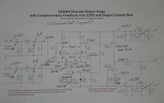
Okay, I've attached a pic of the one of the channels in my DOS. The voltages that matter the most are the ones on each side of R9 and R10. In this channel they are 0.03v different. The other channel is 0.05v different. You want the voltages within a few hundredth's of a volt. You do NOT want the voltages varying by a couple of tenth's
Also take not that I have exactly the same voltages entering the differential. This is the same in both channels.
My voltage readings are not quite perfect, but they are pretty close. I think this is a target to go for.
BTW, my DOS is in my SA-8260 player and not a CD-63/67. It's not really the numbers that matter, it is the relation to each other than matters.
Attachments
When I assembled my (first) DOS board then Ray was kind enough to run a simulation on its schematics when I asked him about what voltages I should be going after (e.g. in the output stage I seem to be running on 8 mA instead of recommended 10 mA - but today it does not hurt my ears one tiny leetle bit ;-) ).
So attached it is.
Next time when I open my player I will perhaps measure what I have got there and post it - just for comparison sake.
So attached it is.
Next time when I open my player I will perhaps measure what I have got there and post it - just for comparison sake.
Attachments
When I assembled my (first) DOS board then Ray was kind enough to run a simulation on its schematics when I asked him about what voltages I should be going after (e.g. in the output stage I seem to be running on 8 mA instead of recommended 10 mA - but today it does not hurt my ears one tiny leetle bit ;-) ).
So attached it is.
Next time when I open my player I will perhaps measure what I have got there and post it - just for comparison sake.
Simulations are always perfect. Actual operating voltages are less so. How close the actual is to the sim determines how well it is operating.
OK, I had some spare time in the weekend so - out of curiocity - I measured the voltages on my active DOS board (see attachment).
Regarding symmetry of the input stage branches - eliminating the difference of 3...4 mV seems kind of serious effort taking into account resistor and transistor manufacturing tolerances etc (all resistors I used are 1%).
Regarding symmetry of the input stage branches - eliminating the difference of 3...4 mV seems kind of serious effort taking into account resistor and transistor manufacturing tolerances etc (all resistors I used are 1%).
Attachments
Need some help checking remote reception of CD67OSE.
When I purchased my CD67OSE aprox 5yrs ago it didn't have a remote so only recently I got one but CD player not responding.
The remote is definately outputting a signal as I can see it flashing when hold in front of my mobile phones camera.
Any advice on what to ceck inside the CD player appreciated.
Tom
Need some help checking remote reception of CD67OSE.
When I purchased my CD67OSE aprox 5yrs ago it didn't have a remote so only recently I got one but CD player not responding.
The remote is definately outputting a signal as I can see it flashing when hold in front of my mobile phones camera.
Any advice on what to ceck inside the CD player appreciated.
Tom
The first thing that comes to mind is that you have had the player in a storage unit for some time and have forgot about the external/internal switch on the rear.
Not been in storage, just never bothered with a remote.
I will have a look this evening at the switch and report back.
Thanks,
I will have a look this evening at the switch and report back.
Thanks,
Not been in storage, just never bothered with a remote.
I will have a look this evening at the switch and report back.
Thanks,
I meant a storage unit/rack where it takes a few seconds to gain access to the rear.
Thanks timjar that worked, I don't actully remember ever seeing that switch before......
Tom
Tom
BIG huge thanks
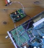
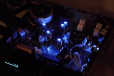
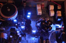
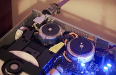
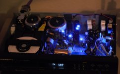
Just finished putting dexa NEUTRON with dedicated psu inside my cd67se
and all i can say it wouldn`t be possible without help of this thread.
Before i started modding my cd i didn`t know how to solder...but now i managed to fit 3 transaformers into this cd and it is all because of wast knowledge here.
Few pictures of my poorly done cd after my work 😀
THANKS for this thread guys. Stay awesome.
Attachments
Marantz is one of the best values going in disc players in the used market. Just before blue ray came out and prior. I have one that sounds cherry, airy and so smooth. its a work house it even plays some rough cd's all others have coughed out. Only mod done to it is suspension feet from reputable turntable.
Just finished putting dexa NEUTRON with dedicated psu inside my cd67se
and all i can say it wouldn`t be possible without help of this thread.
Before i started modding my cd i didn`t know how to solder...but now i managed to fit 3 transaformers into this cd and it is all because of wast knowledge here.
Few pictures of my poorly done cd after my work 😀
THANKS for this thread guys. Stay awesome.
It looks great in there.
- Home
- Source & Line
- Digital Source
- Marantz CD63 & CD67 mods list