Hi,
I think there's another error, the 100 ohm and 10nF capacitor that's connected to pin 3 should be connected to pin 5 instead...?
Also, I don't think the shutdown will work, pin 10 is connected to Ground... which will always enable the chip...
A schematic would really help here 🙂
I think there's another error, the 100 ohm and 10nF capacitor that's connected to pin 3 should be connected to pin 5 instead...?
Also, I don't think the shutdown will work, pin 10 is connected to Ground... which will always enable the chip...
A schematic would really help here 🙂
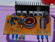
I have built the PSU and it works!
Slight modifications (to make the circuit similar to the one found at ESP):
10k resistors replaced by 12k
Remove one of the 10k resistors immediately above the 3525
Remove the 1k resistor in the same place
Add a 12k resistor from pin 1 to pin 9 of the 3525
Gate resistors changed to 22 ohms
MOSFETs used are Infineon SPP80N06's and output rectifiers are MUR1520s.
The shutdown/standby circuit works, it disconnects power to the chip instead of using the chip's own shutdown input.
Efficiency is >90% (estimated), the (small!) heatsink only gets slightly warm at ~100W output.
I accidentally shorted the output while testing... nothing happened other than a BIG spark.
This will power a pair of Red Rocks Audio D200's 🙂
Attachments

Greetings sharing audisoul first circuit I know the great I am more under construction and I am so worried about the results but I have a few questions using detaylarınıda picture of the transformer to know the shared core diameter of the wire thickness, number of rounds as the winding direction thanks
> swap
> swap
I do not actually know one of the most important issues is how the transformer ever done before and I do not understand how yapıldığınıda English is not my anlıyamıyorum still so you know to share fotoraflarıyla under construction and I would be very happy, thank you
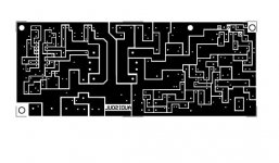
rik89, is it final version of smps PCB? Is it worth trying? Actually, I don't like layout of BYW29 diodes (byw29-200 I suppose), especially jumpers made of wire. Sorry about critics. Is the schematic correct? Sorry for questioning
Rik89, what about R14? Value and power handling? Could you post full schematic? Im conserned about resistors power handling...
Thank you in advance
Thank you in advance
hello world
I finally finished the design of SMPS for this link http://sound.westhost.com/project89.htm
realizatelo and let me know
hello hello
I finally finished the design of SMPS for this link http://sound.westhost.com/project89.htm
realizatelo and let me know
hello hello
Attachments
Help
hi there
Can any one help me about car amplifier active crossover ?
i talk about design hpf-lpf(not variable...just fixed) filter and a little about gain circuit.
Thanks.🙂
hi there
Can any one help me about car amplifier active crossover ?
i talk about design hpf-lpf(not variable...just fixed) filter and a little about gain circuit.
Thanks.🙂
I have a noob question about MOSFET voltage ratings.......
Why is it common to use 75V rated parts? If they are only switching ~14V then why can't a lower voltage part be used; like ~20V?
Why is it common to use 75V rated parts? If they are only switching ~14V then why can't a lower voltage part be used; like ~20V?
theAnonymous1 said:I have a noob question about MOSFET voltage ratings.......
Why is it common to use 75V rated parts? If they are only switching ~14V then why can't a lower voltage part be used; like ~20V?
Anonymous-
These MOSFETs are used in center-tap push-pull type of DC-DC coverters. Since they are almost always rated for 11-16VDC operation, the maximum voltage the main switching MPOSFETs will have to stand off is [Vin(max) + V(turn-off spike, usually 20-40% of Vin)] x 2. So for, at a high line of 16V, that's (16V+6.4V) x 2 = 40.8V. A MOSFET rated at 55V Vdss has sufficient headroom to work here. A Vdss of 75V just gives a bit more headroom. The reason Vin and Vspike are doubled is because for the time the one half of the primary is off (and the opposite is on), the voltage across the "off" half is equal, but opposite, the voltage across the "on" half of the primary, effectively doubling the peak inverse voltage across each MOSFET. Nature of the center-tap push-pull beast.
- Home
- General Interest
- Car Audio
- Making car amplifier SMPS with tl494 + DC Protection