hi luka
I am sorry but I did not understand what you mean.
I apologize for my bad English
bye bye
I am sorry but I did not understand what you mean.
I apologize for my bad English
bye bye
Fets won't fix toroid to sag, thin wire will make voltage drops where they shouldn't be,...
I have also 8 IRFz, and I can tell you if can be diffilculte to get power... I had 472w@ 12.04v, and output was lower then idle by a lot, but my is not regulated...as for core, well you can see for yourself
I have also 8 IRFz, and I can tell you if can be diffilculte to get power... I had 472w@ 12.04v, and output was lower then idle by a lot, but my is not regulated...as for core, well you can see for yourself
hi luka
very very nice work😱 😱
your project is similar to my.
How much power should provide in theory?
how voltage? and current?
and please, post here the schematic and the pcb?
thanks
ps
how do you put such great pictures?
bye bye
very very nice work😱 😱
your project is similar to my.
How much power should provide in theory?
how voltage? and current?
and please, post here the schematic and the pcb?
thanks
ps
how do you put such great pictures?
bye bye
hey,
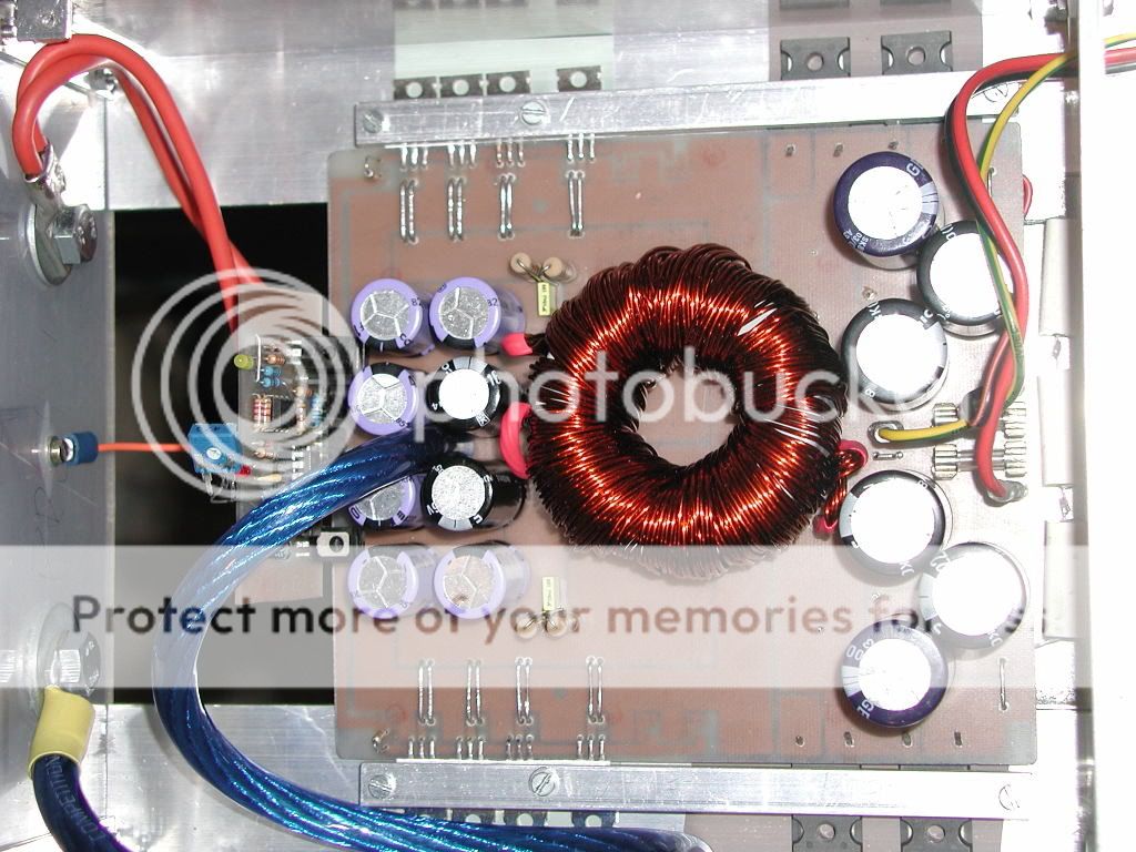
your wire will be the problem, also voltage sag od trafo, I see you do have it regulated, but you will have to see how much will it would hold up
My smps is +/-60v, will probably good up to 1kw, maybe less now, coz I have low freq., something like 23kHz only
I did test is with 12v on input terminal giving constant 472w. now, +/-60v I could get with 13v, at 13.8v or 14.4v it would have to be regulated a bit, just to keep voltage under control. I did test it with AMP2, driving 2 ohme load with on one channel and and playing music... secondary voltage staid always within 0.2v of original idle voltage, so I am very happy...hope to place it into my car one day..
And this is it, basic, my first experimental build
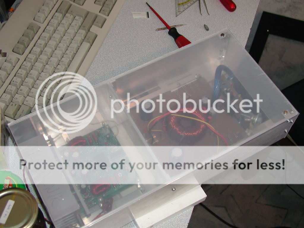
Other projects you can see on my page, thx
your wire will be the problem, also voltage sag od trafo, I see you do have it regulated, but you will have to see how much will it would hold up
My smps is +/-60v, will probably good up to 1kw, maybe less now, coz I have low freq., something like 23kHz only
I did test is with 12v on input terminal giving constant 472w. now, +/-60v I could get with 13v, at 13.8v or 14.4v it would have to be regulated a bit, just to keep voltage under control. I did test it with AMP2, driving 2 ohme load with on one channel and and playing music... secondary voltage staid always within 0.2v of original idle voltage, so I am very happy...hope to place it into my car one day..
And this is it, basic, my first experimental build
Other projects you can see on my page, thx
Hi luka
good work
in your opinion, the power amplifier 4 channel that I made, which supply voltage required? +/-37V or +/-47V?
good work
in your opinion, the power amplifier 4 channel that I made, which supply voltage required? +/-37V or +/-47V?
ok
+/- 37V
i think that 100Wrms for channel on 4 channel amplifier is very good for car audio.What do you think?
Perhaps you know the amplifier schematic? I could not find it, I just pcb
+/- 37V
i think that 100Wrms for channel on 4 channel amplifier is very good for car audio.What do you think?
Perhaps you know the amplifier schematic? I could not find it, I just pcb
that 3R is ok, 16R will have wire wound around this resistor and solderd to same place as resister...Whis wire should be around 1mm, say about 10 turn, and by doing so you will bypass resistor
like so

like so
- Home
- General Interest
- Car Audio
- Making car amplifier SMPS with tl494 + DC Protection