What are some stats I should look for in an oscilliscope? I have a local oscilliscope for sale that is pretty cheap (well under $100) it is 10Mhz scope. I am debating buying this. It is a Lodestar OS-7010A can't find any real stats about it other than having seen a mention somewhere that it was 10Mhz (but it was on a portugese ebay page so I could have misinterpreted it too).yes, nice and slow, get scope, make PCB, build it, see how this really work...
if I would make one now, for testing, learning, I would make critical thing on daughter boards, so you have one universal mainboard, and you can change things, this will be something like control circuit, feedback... this way you only have to redo small control board instead of everything
I would start with unregulated, so you see how trafo should be done... and it is easy to make it really good... then add regulation (which would mean output inductors too)
One thing I would also say, smaller is better, no need to use 1000uF x 10 capacitors on secondarys, since it will make it only bigger and hard to see how something effect regulation
Something in this lines, I how I make any sense, I just woke up
What is the minimum you would go for in an oscilliscope for a beginner looking at doing audio amps and smps type things?
What are some stats I should look for in an oscilliscope? I have a local oscilliscope for sale that is pretty cheap (well under $100) it is 10Mhz scope. I am debating buying this. It is a Lodestar OS-7010A can't find any real stats about it other than having seen a mention somewhere that it was 10Mhz (but it was on a portugese ebay page so I could have misinterpreted it too).
What is the minimum you would go for in an oscilliscope for a beginner looking at doing audio amps and smps type things?
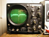
I have an ancient B&K 1460 single trace 10Mhz scope that works fine for my limited needs. I can measure frequency and see how clean the trace is and thats about all I use it for. I have an audio test CD that has 2 minutes of each frequency recorded that I play through the amp with an ordinary cd player that I use as a signal generator. Works well and is super cheap!
Attachments
A 10MHz scope in good working order will be good enough. If you scroll down to the bottom of the following page, you can see a 2MHz compared to a 100MHz.
Basic Amplifier Repair
Basic Amplifier Repair
Winding the core loosely won't cause it to burn traces.
If you can't get the power supply to work properly with the second core, try to find an amplifier to salvage a transformer/core from. Be sure to salvage a core from a transformer, not an inductor.
I don't have anything else to salvage a core from unfourtunately. I'll order a proper core once I start my new job, and I'll tell you all how it turns out.
Hello!
I've just started my smps project. I have question abuot toroid ferites. is suitable ferites from pc maitenance for audio smps? With huge power ferites gets saturation?
I've just started my smps project. I have question abuot toroid ferites. is suitable ferites from pc maitenance for audio smps? With huge power ferites gets saturation?
Hello guys,
I'm new to this forum & was interested in cars smps.
Just wondering any projects for 24V to 12V 180W DC/DC converter?
regards
I'm new to this forum & was interested in cars smps.
Just wondering any projects for 24V to 12V 180W DC/DC converter?
regards
you could use this one too, just use diffrent PRI/SEC turn count
Hello Luka,
Thanks for yr reply.
According to the schematic the input is 12V & converted to +30V,GND,-30V right?
My input is 24V & output is 12V.
so how could I modify the circuit to suit my need?
can upload pcb here?Hi Guys
I have made an amp + smps for my Contessa Classic car.
The smps uses
SG3525 PWM IC
12 X IRFZ44N mosfets
12 X 47ohm Gate resistors
1 X E-I CRGO 4 No. Iron Core Transformer 😛rimary=12-0-12 Multifillar Winding and Secondary 50-0-50 Windings.
one Vero board
2 X 100mFd 25V Caps
2 X 0.1mfd 50V ceramics cap
Couple of other resistors and caps etc.
Frequency is 250Hz
No - Feedback is applied , therefore efficiency is high.
1 X 3.5mFd/250V cap is directly connected to secondary of transformer to suppress spikes.
2 X small heat sinks.
Now the results
No heating on full load only simple warming of sinks
650W power capability
Still alives and is breathing in my car
IF any one interseted mail me.
Hello Risto
thanks for sharing your pcb smps 🙂
but can you share the protel file of the smps please ?
thanks 🙂
thanks for sharing your pcb smps 🙂
but can you share the protel file of the smps please ?
thanks 🙂
RE: pcb file
Hi
Now days i am preparing a web site www.electronica.mk, there I will be upload PCB in .pdf and protel file with full text description. DIY Kit will be also available.
You can also found other dc/dc converters for car audio.
Happy New Year 2011
Hi
Now days i am preparing a web site www.electronica.mk, there I will be upload PCB in .pdf and protel file with full text description. DIY Kit will be also available.
You can also found other dc/dc converters for car audio.
Happy New Year 2011
Hi Risto happy new year too 🙂
It's a great idea but there is a problem, you website have a lot of publicity and link don't work.
for exemple when i click on the "8 Channel PWM LED Chaser" i have publicity
for the Car Power Amplifier Schematic + PCB based on KENWOOD KAC-716 i can't find the protel file and pcb 😕
It's a great idea but there is a problem, you website have a lot of publicity and link don't work.
for exemple when i click on the "8 Channel PWM LED Chaser" i have publicity
for the Car Power Amplifier Schematic + PCB based on KENWOOD KAC-716 i can't find the protel file and pcb 😕
HI
Currently we are updating the web site. It will be ready for one month. Day by day projects will be added to the web site.
Be still you will find asap the pcb in protel.
Currently we are updating the web site. It will be ready for one month. Day by day projects will be added to the web site.
Be still you will find asap the pcb in protel.
Hi Risto happy new year too 🙂
It's a great idea but there is a problem, you website have a lot of publicity and link don't work.
for exemple when i click on the "8 Channel PWM LED Chaser" i have publicity
for the Car Power Amplifier Schematic + PCB based on KENWOOD KAC-716 i can't find the protel file and pcb 😕
Hello, I want to use the smps to get output of 55-0-55 I will be using four mono amps -each 120 Watts Rms @4ohms.2 for stereo and 2 in bridged mode.
I Dont know how to calculate the windings for ferrite core trafo to get 55-0-55. Please guide me.
I Dont know how to calculate the windings for ferrite core trafo to get 55-0-55. Please guide me.
Vin / Np = Vout / Nsec
sORRY but i didnt understand it can you brief it.
Are you sure you want to start this project? This is basic equation! how are you going to calculate anything else, way more important?
Voltage in / number of primary turns = voltage out / number of secondary turns
Voltage in / number of primary turns = voltage out / number of secondary turns
Hello, I want to use the smps to get output of 55-0-55 I will be using four mono amps -each 120 Watts Rms @4ohms.2 for stereo and 2 in bridged mode.
I Dont know how to calculate the windings for ferrite core trafo to get 55-0-55. Please guide me.
Hello Viki_v2,
Please see the sample calculation below:
Assuming:
Vin = 13.8 + 13.8
Np = 4 + 4
Targeted Value:
Vout = 55 + 55
Ns = ?
Formula:
Vin/Np = Vout/Ns
Derived formula to find the value of Ns:
Ns = Vout/ (Vin/Np)
Ns = 110/ (27.6/8)
Ns = 31.88
Ns = 15.94 + 15.94 for center tap configuration.
Check if Vin/Np = Vout/Ns
Vin/Np = 13.8 + 13.8 / 4 + 4 = 3.45
Vout/Ns = 55 + 55 / 15.94 + 15.94 = 3.4
3 or more strands of enamel coated magnet wire will be essential for rewinding to reduce the skin effect.
I hope this information helps.
Regards,
Blueice23
- Home
- General Interest
- Car Audio
- Making car amplifier SMPS with tl494 + DC Protection