Hello
Thanks for this link")
elektronika.com.mk
but i'm french and i dont' speak this language so have you got it in english please ?
and i download the schematic of the pcb to build the dc/dc supply but there is no electronic component list ???
and can you tell me please if i can use this power supply to buil a 4 X 50wrms amplifier for my car ?
Thanks a lot
Thanks for this link
elektronika.com.mk
but i'm french and i dont' speak this language so have you got it in english please ?
and i download the schematic of the pcb to build the dc/dc supply but there is no electronic component list ???
and can you tell me please if i can use this power supply to buil a 4 X 50wrms amplifier for my car ?
Thanks a lot
Hello everybody
As i say previously i'm french and my english is verry bad and i have difficult to understand
So i would like to build my smps power supply, and i found a lot of post talking about that, but i don't know what to do...
Can someone post a file of a good smps power supply who works perfectly, with list of composants to buy and the schematics pcb please ?
Thanks a lot for your help
best regards
hervé.
As i say previously i'm french and my english is verry bad
and i have difficult to understand So i would like to build my smps power supply, and i found a lot of post talking about that, but i don't know what to do...
Can someone post a file of a good smps power supply who works perfectly, with list of composants to buy and the schematics pcb please ?
Thanks a lot for your help
best regards
hervé.
hi
Hi
You should re-wire the transformer in order to cover the whole ferrite core and use bigger wire.
What can cause sound from transformer?
In my case, with larger load sound goes stronger.
Hi
You should re-wire the transformer in order to cover the whole ferrite core and use bigger wire.
I have built the PSU and it works!
I accidentally shorted the output while testing... nothing happened other than a BIG spark.
This will power a pair of Red Rocks Audio D200's
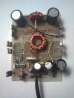
i tried it with the 10uH inductors and the mosfets got really hot and might be blown. I don't know what might be wrong with it right now so im attaching a picture of how it is set up right now. Does anything jump out?
And thanks for the help and the design and everything. I love playing around with this stuff, but my understanding can sometimes be lacking..
And thanks for the help and the design and everything. I love playing around with this stuff, but my understanding can sometimes be lacking..
Attachments
Where did you get the core for the transformer?
From sayal electronics, they have a few stores here in ontario. Cost me a whole dollar
Thank you for looking at it 2pist, it has no voltage at the output with no load though. It's good that nothing stands out besides that though.
with school closed all i have access to is a multimeter. I'm using 47 ohm gate resistors instead of 100 ohm though. The core has 952R 58071-a2 +2 written on the side and what i've been able to find is that it is a high flux core, dimensions are 33.02mm OD, 19.94mm ID, and 10.67mm high. Permeability of 60 according to High Flux Toroidal Cores for Chokes and Inductors : CWS ByteMark, largest supplier of toroids, ferrite cores, iron powder cores, MPP cores and RF cores
that wasnt bright of me... I tried with another toroid i had, a smaller black one with shiny bits in it. No markings or any way to discern what is it though. I tested it and got a reading for a second on the secondary and then a trace to the mosfets burnt out :|
Only one side of mosfets got hot, and they did get very hot.
The trace was to the mosfet's source. I'm assuming the toroid im using now is fine, but either the transformer is not wound tight enough, or the mosfets are toast from testing with the wrong core.
And thanks for taking the time to help with my mistakes
Damn, it has been forever since I have read a double digit paged thread. That being said I just finished reading this one from start to finish. All I can say is THANK YOU to everyone who has contributed here (Perry, Luka, Eva, Risto, etc. etc. etc.). Between the suggested books and everything I have read on here I am reallllly itching to build my own SMPS (gotta get a scope first though...baby steps).
I just figured I would say thanks to those who are sharing their knowledge.
I just figured I would say thanks to those who are sharing their knowledge.
yes, nice and slow, get scope, make PCB, build it, see how this really work...
if I would make one now, for testing, learning, I would make critical thing on daughter boards, so you have one universal mainboard, and you can change things, this will be something like control circuit, feedback... this way you only have to redo small control board instead of everything
I would start with unregulated, so you see how trafo should be done... and it is easy to make it really good... then add regulation (which would mean output inductors too)
One thing I would also say, smaller is better, no need to use 1000uF x 10 capacitors on secondarys, since it will make it only bigger and hard to see how something effect regulation
Something in this lines, I how I make any sense, I just woke up
- Status
- This old topic is closed. If you want to reopen this topic, contact a moderator using the "Report Post" button.
- Home
- General Interest
- Car Audio
- Making car amplifier SMPS with tl494 + DC Protection