Your question has already been answered (multiple times) earlier in this thread. This thread had been jacked by multiple users who are interested in projects that have nothing to do with the LXmini system.I would like to try a first order xovr setup and would like to know how to do that. I know the high and low sections have 2 pole filters for a 2nd. order implementation, but I am not sure which capacitors or resistors to bypass in each section to accomplish a 6 db/octave filter for both high and low pass sections.
Thanks!
Dave.
Last edited by a moderator:
Well, FWIW , the DIY Audiostore ad for the Analog Crossover Network does specifically state
so perhaps not exactly “jacked”, but a separate sticky thread / tutorial walking a neophyte through that process might not hurt. Any volunteers?Nelson Pass has now posted a MicroCap sim file you can use to create crossover simulations for your own loudspeakers. If you have any questions, please post them in the LX-mini Crossover Article
Last edited by a moderator:
I have the lx-mini kit..
...built it a few weeks ago and this is what I am referring to....see my previous posts
...built it a few weeks ago and this is what I am referring to....see my previous posts
Dear mr Pass, referring to post #89, would it perhaps be possible to fabricate the next batch of PCBs to accommodate both DGS and DSG pinouts, just like the B1 board with Korg triode?

...built it a few weeks ago and this is what I am referring to....see my previous posts
Post #258. (That's how you do a first-order crossover.)
LX-mini Crossover Article
Dave.
Last edited by a moderator:
While the crossover was originally designed for the LX mini, one reason it's available in bare bones format without the LX specific components is so that you can use it for projects other than the LX mini. Currently this thread serves the needs of everyone using the crossover. If there's a need to split the thread and certainly if there's a definitive guide/post as to how to design the crossover for other systems that should be linked to from the store's info page, and perhaps worthy of its own thread or guide on guides.diyaudio.com. Any contributions welcome!Your question has already been answered (multiple times) earlier in this thread.
This thread had been jacked by multiple users who are interested in projects that have nothing to do with the LXmini system.
Dave.
Last edited by a moderator:
New thread?
Hello members,
Me and some other forum-members did not want to highjack the LX-minicrossover thread. I understand that there are some different aims. Although the pcbs are the same. 😉
I am completely relaxed and we can open another thread.Perhaps a PASSWORKS AXO custom- thread? Or any other name.
Have a good day!
Dirk
Last edited by a moderator:
PASSWORKS AXO custom - first run
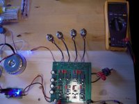
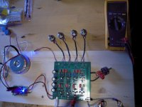
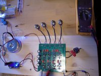
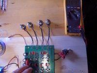
Hello members,
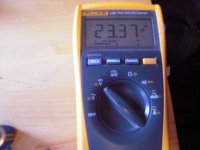
fired up the PASSWORKS AXO first time today. PSU is at 23,37 V under load. I have some offset at the outputs (between 0,7 to 1,3 mV). Will send some sine waves through it. JFETs at 33 - 37 C (temperature).
Greets,
Dirk
Hello members,
fired up the PASSWORKS AXO first time today. PSU is at 23,37 V under load. I have some offset at the outputs (between 0,7 to 1,3 mV). Will send some sine waves through it. JFETs at 33 - 37 C (temperature).
Greets,
Dirk
Attachments
-
 PASS AXO 1st run.jpg112 KB · Views: 956
 -
 PASS AXO JFET temp.jpg118.6 KB · Views: 365
 -
 PASS AXO Voltage.jpg110.1 KB · Views: 247
 -
 PASS AXO Voltage offset output.jpg106.4 KB · Views: 238
 -
 PASS AXO Voltage offset output 3.jpg106.5 KB · Views: 800
 -
 PASS AXO Voltage offset output 2.jpg111.5 KB · Views: 930
 -
 PASS AXO Voltage 3.jpg104.2 KB · Views: 928
 -
 PASS AXO Voltage 2.jpg73 KB · Views: 942
Last edited by a moderator:
Hello ZEN MOD,
thanks for the tip. The 10µF - caps are in there. We will see what happens.
Have a good day!
Dirk
thanks for the tip. The 10µF - caps are in there. We will see what happens.
Have a good day!
Dirk
Last edited by a moderator:
There's a 10k load resistor on the output caps which should drain any residual, so you should measure essentially zero DC offset.
My board measures about 100 microvolts DC (with no signal present) on all the outputs using my Fluke DVM.
Dave.
My board measures about 100 microvolts DC (with no signal present) on all the outputs using my Fluke DVM.
Dave.
Last edited:
Passworks AXO custom - playing music first time
Hello forum members,
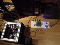
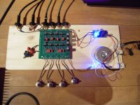
the Passworks AXO custom is playing music! I am running it in. Only playing the LOW-output at the moment (50 - 2500 Hz). Waiting for some new loudspeakercable to wire all fully active.
First impressions are very good.
The baby works! Thanks Nelson Pass!
I measured all the values over the resistors and measurepoints described in Nelson Pass article. Everything in the range. Nice! Very nice machine! But all is still on the wooden proto-board. Next step soundcheck - then lets build a case.
Greets
Dirk
Hello forum members,
the Passworks AXO custom is playing music! I am running it in. Only playing the LOW-output at the moment (50 - 2500 Hz). Waiting for some new loudspeakercable to wire all fully active.
First impressions are very good.
The baby works! Thanks Nelson Pass!
I measured all the values over the resistors and measurepoints described in Nelson Pass article. Everything in the range. Nice! Very nice machine! But all is still on the wooden proto-board. Next step soundcheck - then lets build a case.
Greets
Dirk
Attachments
Last edited by a moderator:

With your First Watt preamps and x-overs, with the external PSUs, do you connect the grounds of the RCAs to the chassis at all? Are these chassis' floating with regard to ground?
Thank you
Thank you
Ooops. I forgot those. Thank you, Mighty ZM.
Yes, I can see that the R0 PCB's ground is connected to the chassis via the four screws. I can also see that at least a few of these design have one RCA ground connected to the chassis (paint/anodizing scraped away).
Yes, I can see that the R0 PCB's ground is connected to the chassis via the four screws. I can also see that at least a few of these design have one RCA ground connected to the chassis (paint/anodizing scraped away).
you can see that from B1 gerbers and other published ones
The gerber link does not work, it just reloads the original page...
PassDiy
- Home
- Amplifiers
- Pass Labs
- LX-mini Crossover Article