X,
From the picture it looks like the 2 PCBs have similarly spaced mounting holes - do these get used in a stacked configuration?
From the picture it looks like the 2 PCBs have similarly spaced mounting holes - do these get used in a stacked configuration?
Hi Zman01,
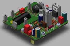
Yes, this will be similar to how we did the OPA454 with the DC/DC boost on the sub-mezzanine level and the preamp on top. Here is the render - I guess I forgot to post it previously.

Once stacked it would sort of look like this except we have the coupling cap on the bottom sub mezzanine board:
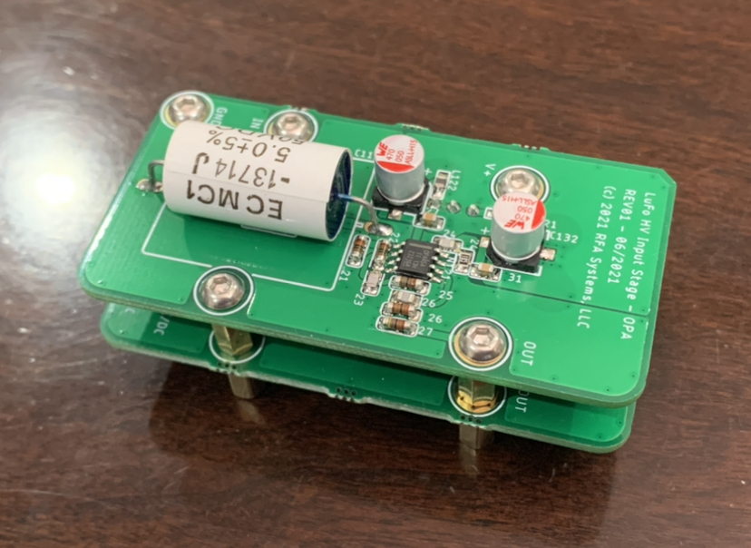
Yes, this will be similar to how we did the OPA454 with the DC/DC boost on the sub-mezzanine level and the preamp on top. Here is the render - I guess I forgot to post it previously.
Once stacked it would sort of look like this except we have the coupling cap on the bottom sub mezzanine board:
Attachments
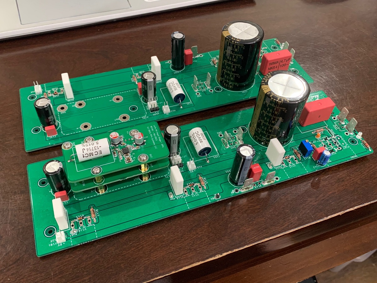
I need to build the second channel of the OPA454 front end board so that I can test out the main LuFO amp on a real chassis.
Hi Zman01,
Yes, this will be similar to how we did the OPA454 with the DC/DC boost on the sub-mezzanine level and the preamp on top. Here is the render - I guess I forgot to post it previously.
Once stacked it would sort of look like this except we have the coupling cap on the bottom sub mezzanine board:
Just to be clear, the idea is to house these in the amp chassis and have them act as a voltage gain stage, rather than use them as a separate preamp?
Yes, they are designed to go right into the LuFo main PCB, like this:
However, since they follow a standard format of the M2X bolt pattern, you could mount them in an M2X amp. Or in an external “breakout” experimenters board or an external preamp main board shown elsewhere.
If you look on Post 1, I show an ACP+ preamp in this format mounted on a breakout board.
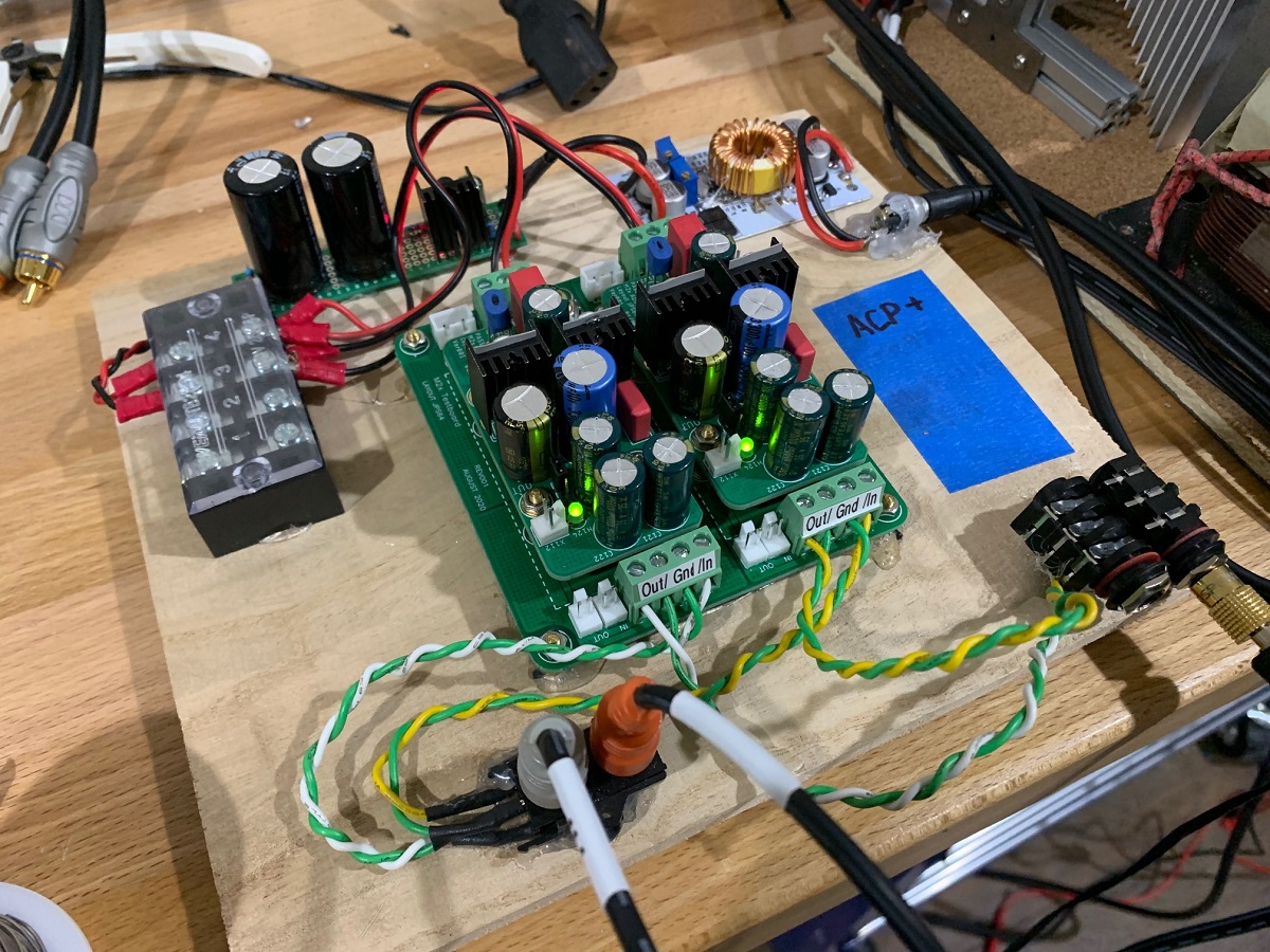
This lets you connect power supply and audio input and output.
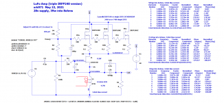
The special thing about these double stack front end boards is that they have a built in ultra quiet DCDC booster that takes the standard PSU rail and converts it to the +55v needed to drive the front end to 50Vpp output swing needed for 39w operation.
However, since they follow a standard format of the M2X bolt pattern, you could mount them in an M2X amp. Or in an external “breakout” experimenters board or an external preamp main board shown elsewhere.
If you look on Post 1, I show an ACP+ preamp in this format mounted on a breakout board.
This lets you connect power supply and audio input and output.
The special thing about these double stack front end boards is that they have a built in ultra quiet DCDC booster that takes the standard PSU rail and converts it to the +55v needed to drive the front end to 50Vpp output swing needed for 39w operation.
Last edited:
I tried something interesting. I connected the free winding to a speaker and it sounded great! Basically a transformer output coupled SE Class A amp with choke load. Maybe sort of like the Zeus but running full Class A. I guess one avoids the output coupling cap this way too.
Hi Mgb1965,
Yes, connect that winding to speaker. You don’t want to short it. It would be like driving a shorted 0ohm speaker.
Btw, I used to drive a 1968 MGB GT. 🙂
Yes, connect that winding to speaker. You don’t want to short it. It would be like driving a shorted 0ohm speaker.
Btw, I used to drive a 1968 MGB GT. 🙂
The prototype for the latest preamp board, the Aksa Lender in Yarra/M2X format has just arrived. This has an on board DC-DC booster to 55v from lower voltages circa 12v to 32v. Another beautiful layout by JPS64. Thank you, JP!
Very nice, any ETA on a Group Buy for the 39W LuFo?
Yes, connect that winding to speaker. You don’t want to short it. It would be like driving a shorted 0ohm speaker.
Thanks, xrk971!
Btw, I used to drive a 1968 MGB GT. 🙂
I have 65 roadster 🙂
Sounds like ZM's bread and butter, X. More IRON!!!! 😀
How much output can you get from that side of the transformer? Still 39W?
How much output can you get from that side of the transformer? Still 39W?
I tried something interesting. I connected the free winding to a speaker and it sounded great! Basically a transformer output coupled SE Class A amp with choke load. Maybe sort of like the Zeus but running full Class A. I guess one avoids the output coupling cap this way too.
It’s using the same stored energy so not sure if one could make a balanced output amp with the half the signal from the cap coupling and the other half with the transformer coupled output.
This might be interesting to see in a simulation.
This might be interesting to see in a simulation.
When you leave the secondary ungrounded you will have a (floating) balanced output.
I am more interested in the winding ratio (easy to measure); likely primary to secondary will be a step down. We are talking about a MOT, right? No idea about winding ratios of those.
When for example the ratio is 3 : 1, instead of the loudspeaker impedance (4 or 8 ohm) the amp will see a load of 4 or 8 times 9 (winding ratio squared) = 36 resp. 72 ohm.
That will cost output power, but be beneficial for distortion.
At the same time DC current can be a factor 3 lower; max output power will drop from 39W to a little over 4W...
In other words, when using an step down output transformer, you must redesign the amplifier (power supply voltage; DC current...)
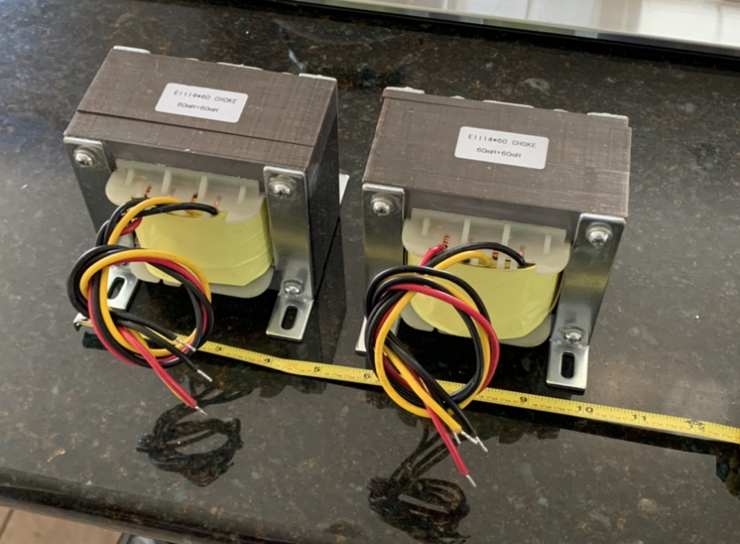
I am talking about the custom balanced inductor. Bifilar winding so same turns ratio. Each winding is 0.48ohm and 60mH at 10kHz and 160mH at 20Hz 14ga copper magnet wire.
With a MOT, one could probably drive STAX headphones with it? It can put out 2500v for microwave ovens.
With a MOT, one could probably drive STAX headphones with it? It can put out 2500v for microwave ovens.
Ah understand; mgb1965 talked about a MOT...
With the 1:1 custom choke you simply replace the output cap with the second winding.
Probably that sounds better.
With the 1:1 custom choke you simply replace the output cap with the second winding.
Probably that sounds better.
I might be wrong.
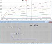
But the LTSpice model for LU1014D used in Post #1 might be problematic.
I couldn't get the wished Id-Vds curve with the model.
But the LTSpice model for LU1014D used in Post #1 might be problematic.
I couldn't get the wished Id-Vds curve with the model.
Attachments
Last edited:
Sorry, I don’t know much about ability to predict the “wished” Id-Vds curve, but the model predicted the DC setpoints and measured distortion of the LuFo amp almost spot on.
Ah understand; mgb1965 talked about a MOT...
With the 1:1 custom choke you simply replace the output cap with the second winding.
Probably that sounds better.
What would be the advantages of transformer coupled output vs cap coupled output? It might be an interesting application when using the 1:1 inductor with a single LuFo board.
- Home
- Amplifiers
- Pass Labs
- LuFo Amp - 39w SE Class A from 28v Rail