Hi Circlotron,
I remember your huge amp now. Those are some inductors you have there! 28v and 3.5A sounds familiar. 🙂

You used MOSFETs instead of the JFET. I also made a 50w choke loaded MOSFET source follower but with slightly different front end following Hugh Dean’s Glass Harmony design.
I remember your huge amp now. Those are some inductors you have there! 28v and 3.5A sounds familiar. 🙂
You used MOSFETs instead of the JFET. I also made a 50w choke loaded MOSFET source follower but with slightly different front end following Hugh Dean’s Glass Harmony design.
As suspected, JPS64 was already on the prowl making a new LuFo Lite board 🙂
It looks wonderful, thank you, JPS64. There are a lot of options on this board such as Fastons, flying leads, or Molex MiniFit connectors for power, speakers, and MOT. There is an option for external heatsink mounted resistor or use the on board “fence post” style triple elevated resistor mount. Having a built in cap multiplier and CRC will give this amp excellent low noise performance and built in slow ramp up to prevent startup speaker pop.
Will there be Gerber files for this amp to?
As it should for the "full" Lufo.
In practice, if we use separate case for tube front end, the same PCB can be used, and only positive signal will be used to drive the LuFo. If we want to put the FE in the same case (tubes can pick up noise and hum from main transformer), then I can remove the voltage regulators and use DC/DC booster. If xrk971 can share the schematic for booster, I can start making a layout. The other option is to have a separate transformer to power up the tube front end.
I prefer the FE in separate case. It gives more flexibility. One can try different power followers, SE, Balanced...
Putting this FE in a separate case gets my vote.
I remember your huge amp now. Those are some inductors you have there!
I remember seeing this amp too. Great to see how audio is intertwined through the years.. dB
In practice, if we use separate case for tube front end, the same PCB can be used, and only positive signal will be used to drive the LuFo. If we want to put the FE in the same case (tubes can pick up noise and hum from main transformer), then I can remove the voltage regulators and use DC/DC booster. If xrk971 can share the schematic for booster, I can start making a layout. The other option is to have a separate transformer to power up the tube front end.
I prefer the FE in separate case. It gives more flexibility. One can try different power followers, SE, Balanced...
Yes, sure I can share the DC/DC booster schematic. Which one are you referring to? The one for the OPA454?
Revised layout for LuFo Lite completed. More space for hot resistors and larger 4700uF output coupling cap. Option for Wima MKP 4.7uF box cap for input and output. Power resistor can be flying leads to heatsinked unit with Fastons or Molex Minifit Jr connectors.
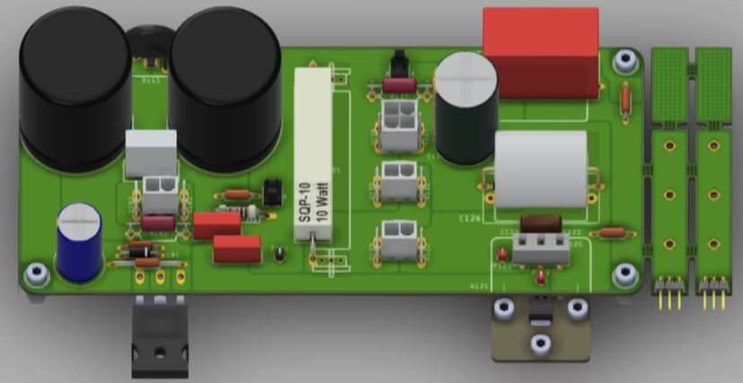
Thank you to JPS64 for another layout masterpiece.
Thank you to JPS64 for another layout masterpiece.
Curious, X. What is the benefit of the larger output coupling cap? Is it just more insurance that no DC will make it to the speakers? Or does it have to do with increased bass response or something else? My Lufo-Lite seems happy with the 2,200uf output cap right now.
Hi Jwjarch,
2200uF cap has -3dB roll off at 9Hz with 8ohm speaker so by 36Hz it’s already starting to fall. 4700uF will make the cutoff at 4.2Hz so 2 octaves above is 16.8Hz - below 20Hz bass which is the lowest we need to go. If you don’t need 20Hz bass then the 2200uF is fine. Certainly even 1000uF is enough for most headphones.
Freq of -3dB for first order RC filter = 1/ (2pi x R x C)
The custom EI balanced winding chokes are in:
SuSyLu Where Are You?

perfect match with Biliar windings (two curves superimposed):

SuSyLu Where Are You?
perfect match with Biliar windings (two curves superimposed):
They look great X!!
I got 2 more MOTs today and can confirm that AMD 101-AMR measure within spec.
Just a static measurement of 85mH and 0.7ohm
dB
I got 2 more MOTs today and can confirm that AMD 101-AMR measure within spec.
Just a static measurement of 85mH and 0.7ohm
dB
Thanks dBel. The laminations moved a bit during transport. They were packed in foam but this is such a dense object I think an impact just made the choke push through the foam and hit whatever it was hard. The measured inductance seems within spec. The DCR is a bit high at 0.88ohm though. They are just samples so we may have to refine the specs and construction before the final order.
Hi Hugh,
Thank you. These inductors turned out nicely I think. That impedance sweep looks very good. The manufacturer tells me he is very confident about the DCR - measured with professional bench LCR meter at 0.484ohms. I will check my DATS calibration to make sure it’s good. 11lbs 5oz is a heavy dense object though.
Here is the air gap under a microscope. The spec was 0.1mm - I am told there is paper used inside to set the spacing before it was glued and bolted together.
Last edited:
Hi X,
What a nice and interesting project to have!
May I know what is the difference between an inductor made with an "air gap" and one made up using the traditional transformer E&I lamination "interlaced" without an air gap.
Thanks.
What a nice and interesting project to have!
May I know what is the difference between an inductor made with an "air gap" and one made up using the traditional transformer E&I lamination "interlaced" without an air gap.
Thanks.
Hi Meanie,
Here is the airgap (I forgot to include in the earlier post):
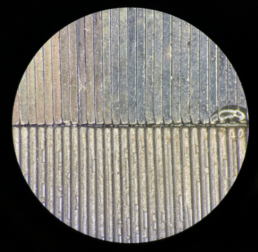
The air gap helps to prevent saturation from a DC field. If you don’t have DC then air gaps are important. Such is the case of a toroidal transformer. Air core inductors don’t have the saturation issue but are huge for the same value of inductance.
Here is the airgap (I forgot to include in the earlier post):
The air gap helps to prevent saturation from a DC field. If you don’t have DC then air gaps are important. Such is the case of a toroidal transformer. Air core inductors don’t have the saturation issue but are huge for the same value of inductance.
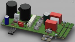
The prototype for the latest preamp board, the Aksa Lender in Yarra/M2X format has just arrived. This has an on board DC-DC booster to 55v from lower voltages circa 12v to 32v. Another beautiful layout by JPS64. Thank you, JP!

Attachments
- Home
- Amplifiers
- Pass Labs
- LuFo Amp - 39w SE Class A from 28v Rail