Sorry, I don’t know much about ability to predict the “wished” Id-Vds curve, but the model predicted the DC setpoints and measured distortion of the LuFo amp almost spot on.
"wished" curve should be Triode like curve in the area Vds 0-5V, Id 0-5A.
The applied model by you is like a normal Mosfet. DC point could be spot on but AC simulation might not be accurate.
Last edited:
![2021-07-29 22_42_08-LTspice XVII - [DEFiLuFet_LU1014D.asc].jpg](/community/data/attachments/878/878293-628538691d06b5e2ebf97f77ff6071b6.jpg?hash=YoU4aR0Gte)
![[DEFiLuFet_LU1014D Id_Vds Tracer Vgs -1.6_-1.2.asc].jpg](/community/data/attachments/878/878297-5f19c8b323fa4b700c29daebb0c1f88c.jpg?hash=XxnIsyP6S3)
Lineup suggested this model that he came up with:
From this thread.
The current model I am using, I pulled off a thread on LU1014D somewhere a long time ago. It would be good to rerun the sims. Although for purposes of designing amp operating setpoints it served its job.
.model LU1014D NJF(Beta=28 Rs=4.6m Rd=4.6m Betatce=-.5 Lambda=.9 Vto=-1.15
+ Vtotc=-2.5m Cgd=363p M=.3805 Pb=.4746 Fc=.5 Cgs=784p Isr=84.77p Nr=2
+ Is=8.477p N=1 Xti=3 Alpha=10u Vk=100 Kf=111.3E-18 Af=1)
From this thread.
The current model I am using, I pulled off a thread on LU1014D somewhere a long time ago. It would be good to rerun the sims. Although for purposes of designing amp operating setpoints it served its job.
Last edited:
![2021-07-29 22_51_39-LTspice XVII - [DEFiLuFet_IRFP240_Cascode.asc].png](/community/data/attachments/878/878307-3e6f73809b04645d43c7c9d8da7ef3f0.jpg?hash=Pm9zgJsEZF)
![[DEFiLuFet_IRFP240_Cascode.asc]Id_Vds_Vgs -1.6_-0.8.jpg](/community/data/attachments/878/878313-53db7b152e6a20b7b08e823b60a32929.jpg?hash=U9t7FS5qIL)
I am not quite sure but suspect that the LTSpice FFT phase is off because I did not tell it to take FFT on steady state data. There is an initial startup transient in the time series.
In the measured data, there is some phase contribution from the preamp (SE Class A discrete - based on Aksa-Lender topology). It is dominant second harmonic but I am not sure if positive or negative phase 2nd harmonic.
In response to post #108:
The phase reported by REW is likely the correct one. I have studied the source code for ngspice and found that it reports phase angles relative to sin basis functions, whereas some or most spectrum analyzers use cos basis functions. This accounts for the phase angle sign difference. To avoid this confusion there is a nice LTSpice tool in the 'Software Tools/Spice simulation' thread: Spice simulation that will extract the correct residual distortion waveform.
Last edited:
Hammond 193v
Hi all,
Does any member have tried the above choke??
How was the result?
Thanks
Albert
Hi all,
Does any member have tried the above choke??
How was the result?
Thanks
Albert
The LuFo is a new development, so not many builders have gotten around to trying different chokes. Quite a few MoFo amps have been built with the 193V, with good results.
I’m running some LTSpice simulations of the LuFo with transformer coupled output and maybe not surprisingly, the distortion decreased. It was 0.01% at 8Vpp into 8ohms and is now 0.009% THD. Still same harmonic profile. The tiny bit of reduction is probably not worth it. However, for those who don’t like capacitor coupled outputs for their speakers, this is now cap free and might sound more transparent.
This tells me that those with MOTs might try to take the HV outputs and see if they can drive a Magnepan or STAX headphones? Be careful with the high voltages though.
This tells me that those with MOTs might try to take the HV outputs and see if they can drive a Magnepan or STAX headphones? Be careful with the high voltages though.
Last edited:
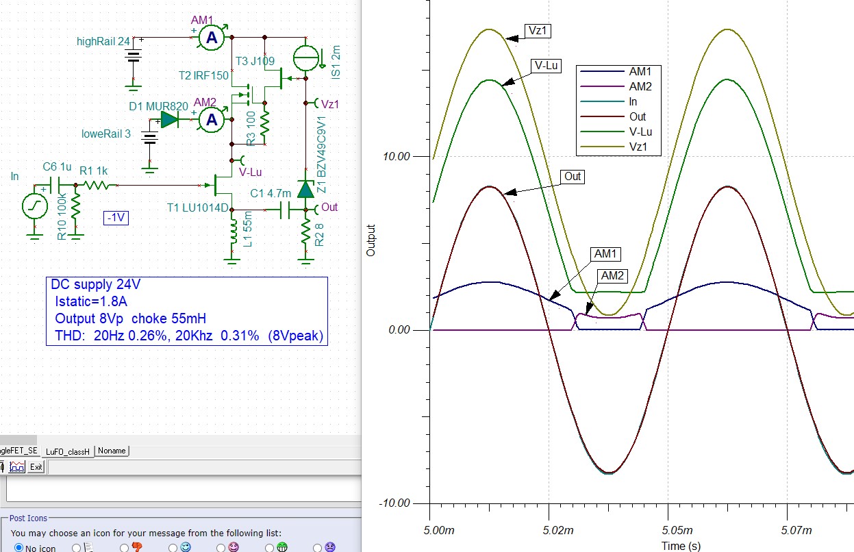
How about LuFo class-G ?
Is the cascode MOSFET in LuFo use be a class-G supply rail ?
Just for reduce heat , if low-rail supply 3Vdc , ths static heat dissipation only 2.3V*2A almost less then 5W.
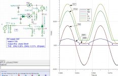
My simulation is work :
Output 8Vp choke 55mH
THD: 20Hz 0.26%, 20Khz 0.31% (8Vpeak on 8R)

Is the cascode MOSFET in LuFo use be a class-G supply rail ?
Just for reduce heat , if low-rail supply 3Vdc , ths static heat dissipation only 2.3V*2A almost less then 5W.
My simulation is work :
Output 8Vp choke 55mH
THD: 20Hz 0.26%, 20Khz 0.31% (8Vpeak on 8R)
Attachments
Can you plot FFT for us? Interesting concept but the whole point of this amp is Class A operation to avoid crossover distortion. Maybe you can build it and tell us how it sounds?
X, I doubt if you understand.
It has nothing to do with class A or not; stoneku's sim is pure class A.
When listening to music at normal SPL, a LuFo (or whatever amp) will output less than 1 watt on average.
The power Jfet could do this by itself without the cascode mosfet turbo on top.
In stoneku's sim most of the time the mosfet is "passive", not dissipating power (and producing heat) when playing music at normal SPL because it's own power supply is "off"; that's how class G works.
When the power is asked, high voltage power supply / mosfet kick in, providing the full power.
This way much less heat is produced.
This is an excellent read to get some insight: Class-G and Class-H
Last edited:
Clearly, I do not understand then. I see a very significant crossover from AM1 and AM2 in the sim and the distortion is significantly higher for 8Vpp - tenths of a percent vs 0.01% THD. Stuff is turning on and off, and in my simple mind, that is not Class A where an active stays on all the time. The JFET may not be turning on and off, but if you take its power supply and switch the rails on and off between two discrete values (a SE Class A amp is dependent on a clean rail), that can't be good for the sound quality.
Last edited:
X, you are right, class-G has switching action , but happened in large signal area.
another idea:
Cascode JFET
In my simulation Cascode will reduce THD more then half, Output 1V on load 8ohms THD from 0.014% reduce to 0.0060%.

another idea:
Cascode JFET
In my simulation Cascode will reduce THD more then half, Output 1V on load 8ohms THD from 0.014% reduce to 0.0060%.
That’s interesting and clever. It might make a fine headphone amp - certainly easy to try.
One reason to use big fat MOSFETs for cascode is that they handle high voltage and can take a lot of dissipation. The bulk of the dissipation is 75w on the cascode vs 8w on the LU. The LU acts as the master or the brain and the cascode is the muscle. Here we have the brain also serving as the muscle. Although I am told these LU’s can dissipate 50w, I would not push them past 20w to keep them from melting (my perhaps, unfounded fear?).
One reason to use big fat MOSFETs for cascode is that they handle high voltage and can take a lot of dissipation. The bulk of the dissipation is 75w on the cascode vs 8w on the LU. The LU acts as the master or the brain and the cascode is the muscle. Here we have the brain also serving as the muscle. Although I am told these LU’s can dissipate 50w, I would not push them past 20w to keep them from melting (my perhaps, unfounded fear?).
Last edited:
Some progress on my Lufo-Lite build. Drilled back panel tonight and mocked up the placement for the major parts.
Attachments
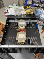
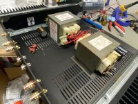
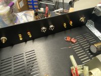
Nice looking chassis there, Jwjarch! I’m surprised you can get the MOTs to fit in such a small chassis.
Thanks X. Trying to get neater with each successive build. The MOTs won’t fit in a 2U without a little ingenuity. The secrets are; no base plate, and shims between the brackets and the bottom cover to create a small gap and extra space. I prefer not to have to shim the top cover, for looks, but I’ll have to test the clearance and see.
Hi X,
That distortion profile looks amazing.
H2 is dominant and H3 is their little bit to add bit of spice.
H4 is their to add pseudo stereo widening effect. Rest of the higher distortion is so low that we cannot hear.
Amazing Amp.
That distortion profile looks amazing.
H2 is dominant and H3 is their little bit to add bit of spice.
H4 is their to add pseudo stereo widening effect. Rest of the higher distortion is so low that we cannot hear.
Amazing Amp.
- Home
- Amplifiers
- Pass Labs
- LuFo Amp - 39w SE Class A from 28v Rail