I wonder if this can work on LuFo Lite? Only 20mH but in series gets 40mH and 1 ohm.
ERSE Super Q 20mH 16 AWG 500W Inductor Crossover Coil
@dibya,
Thanks - yes, it’s a pretty nice classic SE Class A amp harmonic profile. All from about as simple of a circuit as you can get.
ERSE Super Q 20mH 16 AWG 500W Inductor Crossover Coil
@dibya,
Thanks - yes, it’s a pretty nice classic SE Class A amp harmonic profile. All from about as simple of a circuit as you can get.
Last edited:
I could give those a try X. I have a pair in my crossover parts stash. The form factor is certainly smaller than the MOT’s. Is saturation more likely to occur sooner with the ERSE?
It’s a straight iron core so think of it as having a very large air gap. As you have it already, give it a try.
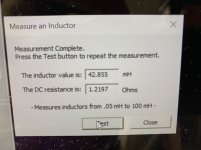
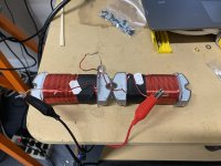
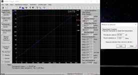
Here’s a DATS measurement on two 20mH ERSE in series. A few more mH. Not a bad thing. Resistance came in a little higher than expected. I assume no added series resistance is needed?
Attachments

Last edited:
It depends on what bias current you are looking for - I am running 1.5R + 0.5R from the MOT. So you might need circa 0.5R more in series. Can you show us what the impedance sweep plot looks like?m
If you stuck them end to end you might eek out a few more mH. 🙂
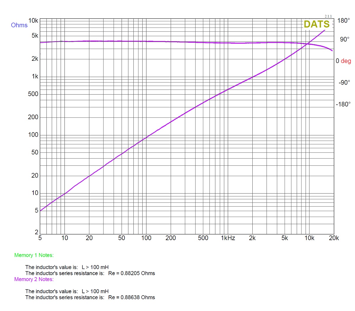
Here is the impedance sweep that I got for my custom made ones. Very linear over audio band with respect to impedance and phase from 20Hz to 20kHz.
If you stuck them end to end you might eek out a few more mH. 🙂
Here is the impedance sweep that I got for my custom made ones. Very linear over audio band with respect to impedance and phase from 20Hz to 20kHz.
Last edited:
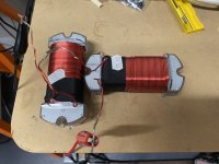
Interestingly enough, X, the highest mH measurement comes from a t-shaped configuration. Side by side or end to end both resulted in about 37mH. T-shape is almost 45mH.
Attachments
Last edited:
That impedance sweep looks awesome! Very linear. Should sound great. Funny that the “T” config helps. When end time end make sure the polarity of the windings is the same.
This appears to be a viable solution for a 45mH 1.2Ohm audio grade inductor for the LuFo.
This appears to be a viable solution for a 45mH 1.2Ohm audio grade inductor for the LuFo.
Can’t take the credit zman. It was X’s idea. I just happened to have a few of the inductors lying around.
I am curious to reverse the polarity on one of them, measure, and report back.
I am curious to reverse the polarity on one of them, measure, and report back.
Ok! Drum roll please!
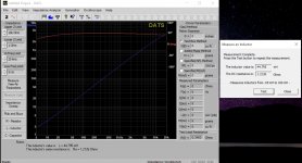
Just took some more measurements on the 20mH ERSE inductors. The magnetic fields are playing some fun tricks. I re-soldered the series connection and took measurements in all the previous positions. One of the higher readings was in fact the end to end at 54mH. I thought, how could I possibly get a higher reading. Then I put them side by side. 71mH!!! Is there any potential downside to this configuration? The impedance sweep is still linear in either configuration.
Just took some more measurements on the 20mH ERSE inductors. The magnetic fields are playing some fun tricks. I re-soldered the series connection and took measurements in all the previous positions. One of the higher readings was in fact the end to end at 54mH. I thought, how could I possibly get a higher reading. Then I put them side by side. 71mH!!! Is there any potential downside to this configuration? The impedance sweep is still linear in either configuration.
Attachments
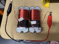

Side by side makes sense since both ends allow the magnetic field to reconnect - sort of like a toroidal choke with two huge air gaps.
71mH and a linear impedance sweep sounds like a winner to me. And it’s quite compact. Not sure how well it will do under full DC load but let’s see how it goes.
It would be interesting to compare the sound quality vs the MOT.
71mH and a linear impedance sweep sounds like a winner to me. And it’s quite compact. Not sure how well it will do under full DC load but let’s see how it goes.
It would be interesting to compare the sound quality vs the MOT.
Here’s a DATS measurement on two 20mH ERSE in series. ... Resistance came in a little higher than expected. I assume no added series resistance is needed?
What's the residual resistance reading if you clamp both crocodiles to the same wire end?
Then take this:
https://www.mouser.ch/ProductDetail/Hammond-Manufacturing/195T10?qs=7rwefYdqV/baug9WE5Qw4w==
It's about the same $/mH ratio.
https://www.mouser.ch/ProductDetail/Hammond-Manufacturing/195T10?qs=7rwefYdqV/baug9WE5Qw4w==
It's about the same $/mH ratio.
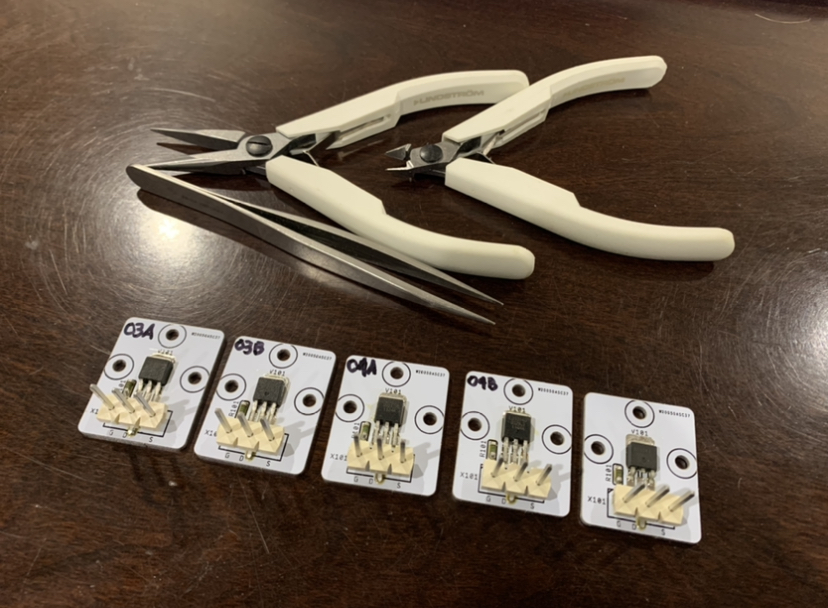
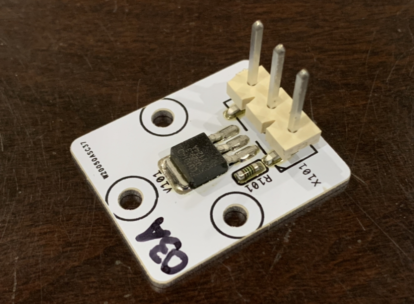
I just soldered another two pairs of matched LU1014Ds onto the aluminum IMS TO-247 adapter PCBs in preparation for a proper LuFo/SuSyLu amp build. The SuSyLu really does need matched pairs to get a balanced current between the two legs.
Can you mount (solder ) them with a hot air gun?
Russet, I’ve had success with a hot air gun, heating the pcb from the underside and then just touching the pads with my soldering iron. So yes, it can be done without the hot plate.
- Home
- Amplifiers
- Pass Labs
- LuFo Amp - 39w SE Class A from 28v Rail